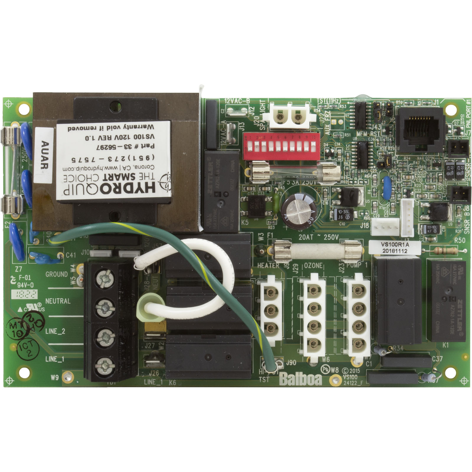
Balboa VS100 Spa Circuit Board — 56297-02 — Single-Pump 120V/240V Control System
$249.05
Fast dispatch
Order in
--:--:--
for shipping today
🔌 Balboa VS100 Spa Circuit Board — 56297-02 — Single-Pump 120V/240V Control System
Professional-grade replacement board for reliable VS100 single-pump spa control and performance.
⚠️ IMPORTANT — DISCONTINUED PRODUCT
This board (56297-02) has been discontinued by Balboa Water Group. The current in-stock replacement is the Genuine Balboa VS100 / RS101 — G1110 (available here).
The G1110 is a direct functional replacement using the same VS100C PCB (PN 24084 Rev B) and is fully compatible with all original VS100 topside panels and system wiring.
If you need the 56297-02 specifically, contact Parts4Tubs — limited legacy stock may be available.
📋 Product Overview
The Balboa VS100 circuit board (Part Number 56297-02) is a genuine Balboa Water Group OEM PCB for the VS100 single-pump spa control system, built on the VS100C PCB platform (PN 24084 Rev B). Designed for compact single-pump hot tubs and portable spas, this board manages a two-speed Pump 1, a 10V spa light, a 120V ozone output, and a flow-through heater — all through a compact 10-position DIP switch configuration.
The VS100 control system accepts 240VAC / 60Hz service while operating the pump and ozone at 120V (between one hot leg and neutral). The heater runs at 240V for a full 4.0kW output. In a 120V GFCI cord configuration, the heater outputs approximately 1.0kW.
Note: This product has been superseded by the Genuine VS100 G1110. The G1110 is the recommended replacement and is currently in stock.
✨ Key Features
✅ Genuine Balboa Water Group OEM PCB — VS100C, PCB PN 24084 Rev B
✅ Two-Speed Pump 1 Control — 120V, high and low speed
✅ 240V Service / 120V Pump & Ozone — unique mixed-voltage architecture
✅ 4.0kW Heater at 240V — (1.0kW at 120V configuration)
✅ Ozone Output — 120V factory-configured, operates with Pump 1 Low (J29)
✅ 10V Spa Light Output
✅ DIP-Switch Configurable — 10-position Switchbank A (A1–A10)
✅ Persistent Memory (J43) — battery-free storage of set temp, filter settings, heat mode
✅ Multiple Topside Panel Options — VL200, VL240, VL260, VL401, VL403
✅ Priming Mode — automatic pump protection on startup
✅ Class A GFCI Compatible
✅ Made in USA — Balboa Instruments, Inc.
✅ 1-Year Manufacturer Warranty
⚙️ Technical Specifications
| Specification | Value |
|---|---|
| Part Number | 56297-02 |
| Current Replacement | G1110 (Genuine VS100) |
| PCB Part Number | VS100C — PN 24084 Rev B |
| System PN | 56298-02 |
| System Model | MP7-VS100-GCAK |
| Software Version | 41 |
| SSID | 100 — 59 — 41 |
| Board Type | Single-pump main spa control PCB |
| Service Voltage | 240VAC / 60Hz (hardwired); 4-wire |
| Service Amperage | 30A |
| Max Breaker | 40A |
| GFCI | Class A, required per NEC Article 680 |
| Heater Output @ 240V | 4.0kW |
| Heater Output @ 120V | ~1.0kW |
| Pump 1 Output | 120V, 2-Speed |
| Pump 2 / Blower | Not available — single-pump board |
| Ozone Output | 120V at J29 — factory configured |
| Spa Light Output | 10V |
| DIP Switches | Switchbank A: 10 positions (A1–A10) |
| Fuse F1 | 20A 250V |
| Fuse F2 | 0.25A (T) 250V |
| Fuse F5 | 3A 250V |
| TB1 Torque | 27–30 in. lbs. (31.1–34.5 kg·cm) |
| Minimum Wire | #6 AWG, 90°C rated |
| Wire Type | Copper conductors only |
| Warranty | 1 year (manufacturer) |
⚠️ “115V” in the product name refers to the pump and ozone operating voltage (120V/115V leg). The service supply is 240V/60Hz. Do not connect this board to a 120V-only supply without appropriate configuration.
🔗 Compatibility Guide
Compatible Topside Panels:
| Panel PN | Panel Name | DIP A3 Setting |
|---|---|---|
| 55123 | VL200 (Mini Panel) | DIP A3 ON |
| 55080 | VL240 / MVP240 | DIP A3 OFF |
| 55081 | VL260 / MVP260 | DIP A3 OFF |
| 54665 | VL401 (LCD Lite Duplex / Lite Digital) | DIP A3 OFF |
| 54664 | VL403 (LED Lite Duplex / Lite Digital) | DIP A3 OFF |
⚠️ DIP A3 must be set correctly to match your panel type. A3 ON = Mini Panel (VL200); A3 OFF = all others. ⚠️ Panels with A2 or A3 ON are not compatible with each other — panel button layouts are mutually exclusive.
Replaces / Cross-Reference Part Numbers:
| Part Number | Description |
|---|---|
| 56297-02 | This board (original MPN) |
| 56298-02 | System PN for VS100 |
| 56299-01 | Base PCBA PN for VS100 |
| G1110 | Current Genuine VS100 replacement (recommended) |
| 24084 Rev B | PCB VS100C bare board number |
| 56298-03 | VS100 System (220V setup) |
| 54805 / 10-175-4805 | VS100 System (220V setup) |
| 56473 | VS100 System |
| 54808 | VS100 Kit |
| 54825 | VS100 System (No GFCI) |
| 56296-03 | VS100 System with GFCI |
| 10-175-4821 | VS100 System variant |
| 54660-01 / 56439-03 | VEL100SB Board / System |
| 56403 / 456404-01 | RS101 (Dream Maker Spas) |
| 53946 / 462015 | RS100 Circuit Board |
| 53947 | RS100 System |
Compatible Spa Applications:
| Brand / System | Notes |
|---|---|
| VS100 system spas (general) | ✅ Primary application |
| RS100 system spas | ✅ Confirmed replacement |
| RS101 / Dream Maker / AquaRest Spas | ✅ Confirm 110V pump and ozone circuit |
| Premium Leisure Ultra Spa | ✅ Confirmed |
| GS100-based spas | ✅ Compatible |
🎛️ Board Functions & Controls
Output Summary:
| Output | Voltage | Notes |
|---|---|---|
| Pump 1 | 120V, 2-Speed | Main jet pump; no Pump 2 or blower |
| Ozone | 120V | J29; factory-configured; runs with P1 Low |
| Spa Light | 10V | J20 |
| Heater | 4.0kW @ 240V / ~1.0kW @ 120V | Flow-through; M7 sensors |
DIP Switchbank A (PDF-CONFIRMED):
| Switch | OFF | ON |
|---|---|---|
| A1 | Test Mode OFF (normal) | Test Mode ON |
| A2 | Button layout: Unused / P1 / Temp / Light | Button layout: P1 / Light / Temp Down / Temp Up |
| A3 | Lite Duplex / Digital Duplex panel | Mini Panel (VL200) |
| A4 | N/A — must remain OFF | must remain OFF |
| A5 | P1 high-speed timeout — see Table 1 | P1 high-speed timeout — see Table 1 |
| A6 | 60Hz (US normal) | 50Hz |
| A7 | Std / Ecn / Sleep mode changes allowed | Standard mode only |
| A8 | Fahrenheit | Celsius |
| A9 | P1 low-speed timeout — see Table 1 | P1 low-speed timeout — see Table 1 |
| A10 | High amp mode (heat runs with P1 high) | Low amp mode (heat OFF with P1 high) |
⚠️ A4 and A9 are N/A — must always remain OFF. Do not enable these.
Pump 1 Timeout Table (A5 + A9):
| A5 | A9 | Low-Speed Timeout | High-Speed Timeout |
|---|---|---|---|
| OFF | OFF | 2 hours | 15 min |
| ON | OFF | 2 hours | 30 min |
| OFF | ON | 15 min | 15 min |
| ON | ON | 30 min | 30 min |
Key Jumpers / Connectors:
| Connector | Function |
|---|---|
| J43 | Persistent Memory: 2 pins = RESET; 1 pin = Enabled |
| J29 | Ozone output (120V, factory configured) |
| J23 | Pump 1 |
| J9 | Heater |
| J1 | Topside control panel |
| Sensor A / B | Hi-limit and temperature sensor inputs |
| TB1 | Main power terminal block |
🛠️ Installation Requirements
⚠️ Installation must be performed by a licensed electrician in compliance with NEC and all applicable local codes.
Pre-Installation Checklist:
- [ ] Confirm your board PN matches 56297-02 or cross-references listed above
- [ ] Note all DIP switch positions on the old board before removal
- [ ] Disconnect all power at the GFCI breaker or disconnect
- [ ] Allow 5 minutes for capacitor discharge after power-off
- [ ] Photograph all wiring connections
- [ ] Confirm your supply voltage (240V or 120V) and configuration
- [ ] If switching to G1110 replacement: verify topside panel compatibility (same)
Electrical Requirements:
| Requirement | Specification |
|---|---|
| Supply Voltage | 240VAC / 60Hz |
| Service Amperage | 30A |
| Max Breaker | 40A |
| GFCI | Class A GFCI — NEC Article 680 |
| Wiring | 4-wire: Hot (Black), Hot (Red), Neutral (White), Ground (Green) |
| Ground & Bonding | Required — NEC Article 680 |
| Dedicated Circuit | Required |
| Disconnect | Within line of sight, at least 5 ft from spa |
| Wire Type | Copper conductors ONLY, #6 AWG min., 90°C rated |
| TB1 Torque | 27–30 in. lbs. |
Wiring Voltage Configuration:
- Pump 1 and Ozone: 120V (between Line 1/Black and Neutral/White)
- Heater: 240V (between Line 1/Black and Line 2/Red) → 4.0kW output
Persistent Memory Reset (REQUIRED after any DIP change except A1):
- Power down the spa
- Place jumper across J43 covering both pins
- Power up — wait for the ready indicator on the panel
- Power down again
- Remove jumper from J43 (or move to 1 pin only)
- Power up — new DIP settings active
⚠️ Safety Warnings
- ⚠️ ALWAYS disconnect all power before board work
- ⚠️ Licensed electrician installation required; NEC Article 680 compliance mandatory
- ⚠️ Class A GFCI required; grounding and bonding required per NEC Article 680
- ⚠️ 240V service required — 30A / 40A max breaker; 4-wire connection
- ⚠️ Pump and ozone operate at 120V — devices on these outputs must be rated 120V
- ⚠️ Heater operates at 240V — heater must be rated for 240VAC
- ⚠️ DIP A4 must always remain OFF — enabling it causes system damage
- ⚠️ Reset Persistent Memory (J43) after any DIP change or new settings will not activate
- ⚠️ Use copper conductors only — #6 AWG minimum, 90°C rated
- ⚠️ Torque TB1 to 27–30 in. lbs. only — do not over-tighten
- ⚠️ This board is DISCONTINUED — the G1110 is the recommended in-stock replacement
🔍 Power-Up Diagnostics
| Display | Meaning |
|---|---|
| SSID (100 — 59 — 41) | System Software ID, Version 41 |
| “GC” | Heater 3–6kW range — normal at 240V |
| “CG” | Heater 1–3kW range — normal at 120V |
| Priming mode | Normal startup |
❓ Frequently Asked Questions
Q: This board is discontinued — what should I order instead? A: Order the Genuine Balboa VS100 / RS101 — G1110, available now at Parts4Tubs. It uses the identical VS100C PCB (PN 24084 Rev B), same SSID, same DIP switch configuration, and is fully compatible with all the same topside panels and system wiring.
Q: Why does the title say “115V” if the service is 240V? A: “115V” refers to the pump and ozone operating voltage. The VS100 accepts a standard 240V / 4-wire service, but the pump and ozone connectors are wired to operate at 120V (between one hot leg and neutral). The heater runs at full 240V for 4.0kW output. This mixed-voltage architecture is by design.
Q: Can this board control a second pump or blower? A: No. The VS100 platform supports one pump (Pump 1, 2-speed) only. There is no Pump 2 or blower relay. If your spa requires these, contact Parts4Tubs for an appropriate board recommendation.
Q: What DIP setting selects the Mini Panel (VL200)? A: DIP A3 must be set to ON to use the VL200 Mini Panel. For all other panels (VL240, VL260, VL401, VL403), DIP A3 must be OFF.
Q: After I change DIP switches, my spa isn’t behaving correctly. What do I do? A: Perform a Persistent Memory reset via J43. Any DIP change except A1 requires this reset to take effect. See the Installation section for the full procedure.
✅ Why Choose the Balboa VS100 56297-02
✅ Genuine Balboa Water Group OEM PCB — VS100C, PN 24084 Rev B
✅ Mixed-voltage design — 240V service with 120V pump/ozone + 4.0kW 240V heater
✅ All five Balboa VL-series panels supported — VL200 through VL403
✅ RS100 and RS101 system compatible — broad legacy coverage
✅ Field-configurable via 10-position DIP switchbank
✅ 1-year manufacturer warranty
⚠️ This board is discontinued. For new orders, the G1110 Genuine VS100 is the recommended in-stock replacement.
🤝 Why Buy from Parts4Tubs
✅ Fast US shipping
✅ Expert technical advice from spa specialists
✅ Competitive pricing
✅ Full warranty support
✅ Compatible VL-series topside panels, sensors, and heaters available
✅ Help identifying the correct board — 56297-02 vs G1110 guidance provided
🔌 Summary
The Balboa VS100 circuit board (56297-02, VS100C PCB PN 24084 Rev B) is a single-pump OEM spa control board operating on 240V/60Hz service, with pump and ozone running at 120V and the heater at 4.0kW / 240V. It controls Pump 1 (2-speed, 120V), a 10V spa light, a 120V ozone generator, and a flow-through heater. No Pump 2 or blower is supported. Five Balboa VL-series panels are compatible, with DIP A3 selecting between Mini Panel (ON) and Duplex-style panels (OFF). This product is discontinued — the current in-stock replacement is the Genuine VS100 G1110, which is identical in specifications and fully interchangeable.
Finding and identifying a replacement Hot Tub Circuit Board (PCB)
If you are looking to replace a failed PCB on your Hot Tub’s spa pack, then quite often identifying the part that you need can be the hardest thing.
Firstly, you are looking for a model number on the actual circuit board itself. Having the model or serial of your hot tub is not going to help at this point, you need to find the number on the PCB itself.
Now, with certain brands of PCB, the number of the replacement PCB that you need is not going to match identically the one you are replacing. Why is that I hear you ask?
Well, normally, it is an updated version. This means that it might have updated firmware on the PCB or be a later revision. Normally, this means that the part number would be slightly different. This is usually indicated with a “12345678 -x” at the end of that part number where x indicated a firmware revision.
In some cases, there will be some following letters on the part number of the circuit board, “12345678 -x MAS” this can indicate that the PCB was used for an OEM meaning it was produced for a certain hot tub manufacturer and the letters identify the manufacturer.
This means if you source an original PCB, it will not have the letters, but will in most cases work just fine.
It can be confusing I know!
What if you can’t find a model number?
If you can’t find a model number on the PCB itself, then you need to look for a model number on the spa pack. Normally, there is a sticker on the outside of the spa pack that tells you the current ratings and input voltages etc and this will have a model number.
In general, most spa packs in the USA are manufactured by Balboa, Hydro-Quip, ACC or Gecko. I know I am generalising here, but if you have a spa pack that has the brand of your hot tub on, it will be an OEM so the key is identifying who made the original box.
From there, you can normally find an original PCB that you will be able to switch out.
For example, the Balboa VS (value series) is a very popular spa pack that has been used by multiple hot tub manufacturers under their own brand names. Whatever they have called it, strip it back and it is still a Balboa VS.
Visual Inspection
One of the most important things you can do when you are looking for a replacement is to visually inspect the PCB that you have versus the picture online of the replacement you are considering. They need to look the same even if there are the differences in firmware revisions or OEM part numbers, you should be visually replacing a PCB that looks like the one you have.
Configuring a replacement Hot Tub Circuit Board (PCB)
When you get a new PCB, you are more than likely going to need to configure it. Most PCBs have a number of different modes and setups that the can operate in. For this, you will need to manual or spec sheet to guide you.
For things like DIP switches, most of the time you can copy the settings from your original circuit board. You are looking for things like setting the voltage as a lot of PCBs can be configured to run on both 115V and 230V.
You may need to move jumpers or even wires to configure voltages – the key here is that you read the schematic and don’t expect the PCB to just work out of the box – it usually doesn’t.
Troubleshooting a Hot Tub Circuit Board (PCB)
Here are some common things you will see when you replace a PCB on a hot tub.
You press the buttons on the topside control and they don’t control the right parts (pumps or blower etc) – this is a mode configuration thing and you will either need to change some DIP switches on the PCB or an internal or low level programming mode on the topside control. Check the manual for how to do this.
You turn on the hot tub and it trips the breaker – it is not common for a new PCB to fail out of the box (I have not seen one yet!) However, a common mistake is that the voltage has not been set correctly. If it is set for 115V and then you try and turn it on, the current draw will be a lot more (twice) than expected and the breaker will trip.
To check this, unplug all of your kit – heater, pumps, blower and then turn on the PCB. If it trips with nothing plugged in, usually the voltage is incorrectly set and what is happening is that live current is being sent to the ground – because you have 4 wires into the PCB rather than 3. Current on the ground loop causes the trip. Check the settings to make sure it is configures for 230V.
It might not trip until you physically turn on a pump or a blower. As mentioned, if the pack is set to 115V and your pump is meant for 230V, it will draw twice the current at half the voltage and trip your breaker. Check the manual for info on how to set the voltage.
| Circuit Board Application | Balboa Water Group |
|---|---|
| Circuit Board Model | VS100 |
| Circuit Board Type | New |
| Manufacturers Part Number | 56297-02 |
| H Part# | 59-355-1901 |
Related products
Waterway Topside Controls
$232.19
Hydro-Quip Spa Controls
Hydro-Quip Outdoor Series 5.5kW 230V Flow Thru Heater 26-0053-F-M7-KS
$185.33
Balboa Circuit Boards
Coleman / MAAX 100 Series Spa Circuit Board — 101285 (Chip 115/7R1x)
$463.36
Out of stock
Balboa Topside Controls (Overlays)
$215.80
Gecko Spa Pack Controls
$343.01

Sundance Circuit Boards
Sundance® / Jacuzzi® 6600-297 J-300 LED Series Spa Circuit Board (2-Pump, CLEARRAY® On-Demand)
$590.80
Out of stock
Hydro-Quip Spa Pack Controls
Hydro-Quip M1 Spa Control 1.0/4.0kW Low Flow Heater CS9234M1-F-U-LF
$987.06
$481.65