

Balboa VS100 / RS101 Spa Circuit Board — G1110 (PCB VS100C) — Single-Pump 120V/240V Control System
$281.89
153 in stock (can be backordered)
Fast dispatch
Order in
--:--:--
for shipping today
⚡ Balboa VS100 / RS101 Spa Circuit Board — G1110 (PCB VS100C) — Single-Pump 120V/240V Control System
OEM-quality circuit board engineered for reliable single-pump spa control and performance.
💧 Product Overview
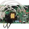
The Balboa VS100 spa circuit board (PCB VS100C, Part No. 24084) is a genuine Balboa Water Group replacement PCB designed for compact single-pump hot tub and portable spa control systems. This board serves as the brain of the VS100 control system, managing a two-speed Pump 1, spa lighting, an ozonator, and a flow-through heater — all from a space-efficient, reliable circuit board platform.
Compatible with the full range of Balboa VL-series topside panels (VL200, VL240, VL260, VL401, and VL403), the VS100 PCB is a direct replacement for spas originally equipped with the Balboa VS100, RS100, or RS101 control systems. It is well suited to compact entry-level hot tubs where simplicity, efficiency, and dependable operation are priorities.
Whether your current board has failed due to water damage, component burnout, or age-related wear, this genuine Balboa PCB restores full spa functionality with a like-for-like replacement. Manufactured by Balboa Water Group — the world’s leading spa control manufacturer — this board is engineered to the same standards as the original equipment.
✨ Key Features
✅ Genuine Balboa Water Group PCB — OEM-quality board, not an aftermarket imitation; ensures full system compatibility and reliability
✅ Two-Speed Pump 1 Control — Supports a standard two-speed main jet pump for both low-speed filtration and high-speed jet operation
✅ Dual Voltage Operation — Supports both 120V/60Hz (1.0kW heater) and 240V/60Hz (4.0kW heater) configurations via wiring setup
✅ Integrated Ozone Output — Factory-configured 120V ozone connector (J29); ozone runs with Pump 1 Low speed
✅ Spa Light Output — Built-in 10V light output for spa illumination control
✅ Multiple Compatible Topside Panels — Works with Balboa VL200, VL240 (MVP240), VL260 (MVP260), VL401, and VL403 topsides
✅ DIP-Switch Configurable — 10-position switchbank (A1–A10) allows field adjustment of pump timeouts, display mode, panel layout, and amp mode
✅ Persistent Memory — Stores filter settings, set temperature, and heat mode without a battery; easy reset via J43 jumper
✅ Priming Mode at Power-Up — Automatic priming sequence protects pump on initial startup
✅ Class A GFCI Compatible — Designed to operate on Class A GFCI-protected service per NEC Article 680
✅ Made in the USA — Balboa Water Group, manufactured in the United States
✅ Compact Board Footprint — Space-efficient PCB suitable for tight spa equipment enclosures
⚙️ Technical Specifications
| Specification | Value |
|---|---|
| Manufacturer Part Number | G1110 (current) / 24084 Rev B (PCB VS100C) / 56297-02 (legacy) |
| System Part Number | 56298-02 |
| System Model | MP7-VS100-GCAK |
| Software Version | 41 |
| Board Type | Main Spa Control PCB |
| Input Voltage | 240V/60Hz (standard hardwired) or 120V/60Hz (GFCI cord configuration) |
| Service Required (240V config) | 30A, Class A GFCI-protected, 4-wire (Hot, Hot, Neutral, Ground) |
| Max Breaker Rating (240V config) | 40A |
| Heater Output (240V supply) | 4.0kW @ 240VAC |
| Heater Output (120V supply) | 1.0kW @ 120VAC |
| Pump 1 Output | 2-Speed, 120V |
| Pump 2 | Not available on this board |
| Blower Output | Not available on this board |
| Ozone Output | Yes — 120V, factory configured, J29 connector |
| Light Output | 10V |
| DIP Switches | 10 positions (Switchbank A, A1–A10) |
| Fuse F1 | 20A, 250V |
| Fuse F2 | 0.25A (T), 250V |
| Fuse F5 | 3A, 250V |
| Persistent Memory Reset | J43 jumper |
| Wire Type | Copper conductors only |
| Minimum Wire Gauge | #6 AWG, 90°C-rated minimum |
| Terminal Block Torque (TB1) | 27–30 in. lbs. (31.1–34.5 kg·cm) |
| Certifications | See manufacturer documentation |
| Warranty | Contact Parts4Tubs for current warranty terms |
⚠️ Always verify your spa’s electrical configuration before ordering. Voltage and wiring must match board configuration. Do not assume.
ℹ️ US Voltage Note: The VS100 board is designed for US 120V/60Hz or 240V/60Hz residential service. Never connect to 50Hz international power supply.
🔗 Compatibility Guide
Replaces the Following Control Systems and Boards:
| OEM / Legacy Part Number | Description |
|---|---|
| 56297-02 | Balboa VS100 Circuit Board |
| 56298-03 | VS100 System (220V Setup) |
| 54805 / 10-175-4805 | VS100 System (220V Setup) |
| 56473 | VS100 System |
| 54808 | VS100 Kit |
| 54825 | VS100 System (No GFCI) |
| 56296-03 | VS100 System with GFCI |
| 10-175-4821 | VS100 System variant |
| 54660-01 / 56439-03 | VEL100SB Board / System |
| 56403 / 456404-01 | RS101 (Dream Maker Spas) |
| 53946 / 462015 | RS100 Circuit Board |
| 53947 | RS100 System |
⚠️ Always verify your existing board part number before ordering. Compatibility for RS100/RS101 replacements may require 110V pump and ozone circuits — confirm your system configuration.
Compatible Topside Panels:
| Panel Part Number | Panel Name | Notes |
|---|---|---|
| 55123 | VL200 (Mini Panel) | DIP switch A3 must be ON |
| 55080 | VL240 / MVP240 | DIP switch A3 must be OFF |
| 55081 | VL260 / MVP260 | DIP switch A3 must be OFF |
| 54665 | VL401 (Lite Digital / LCD Lite Duplex) | DIP switch A3 must be OFF |
| 54664 | VL403 (LED Lite Duplex) | DIP switch A3 must be OFF |
Compatible Sensors:
| Part Number | Description |
|---|---|
| 25283 / 25-175-5283 | Balboa M7 Temperature / Hi-Limit Sensor |
| 26-150-0202 | Balboa M7 Sensor |
🎛️ Board Functions & Controls
Pump Control:
| Output | Function | Configuration |
|---|---|---|
| Pump 1 | Two-speed main jet pump | 120V, high and low speed |
| Pump 2 | Not available | No second pump on VS100 |
| Blower | Not available | No blower on VS100 |
Heater Control:
| Feature | Specification |
|---|---|
| Heater Type | Flow-through electric element (M7 / remote heater) |
| Max Output (240V supply) | 4.0kW @ 240VAC |
| Max Output (120V supply) | 1.0kW @ 120VAC |
| Hi-Limit Protection | Yes — via Sensor A (hi-limit) and Sensor B (temperature) inputs |
Additional Controls:
| Function | Capability |
|---|---|
| Ozone | 120V output, factory configured, runs with Pump 1 Low speed |
| Spa Light | 10V output |
| Persistent Memory | Stores set temp, filter settings, heat mode (battery-free) |
| Time of Day | Not supported on VS100 (Serial Deluxe panels only, not compatible) |
DIP Switch Summary (Switchbank A):
| Switch | Function |
|---|---|
| A1 | Test Mode (normally OFF) |
| A2 | Panel button layout (ON = P1/Lt/Temp Down/Temp Up; OFF = Unused/P1/Temp/Lt) |
| A3 | Panel type (ON = Mini Panel VL200; OFF = Lite Duplex/Digital Duplex) |
| A4 | N/A — must remain OFF |
| A5 | Pump 1 high-speed timeout (see table) |
| A6 | Hz selection (ON = 50Hz; OFF = 60Hz) |
| A7 | Mode changes (ON = Standard only; OFF = Std/Ecn/Sleep allowed) |
| A8 | Temperature display (ON = Celsius; OFF = Fahrenheit) |
| A9 | Pump 1 low-speed timeout (see table) |
| A10 | Amp mode (ON = Low amp / no heat with P1 Hi; OFF = High amp / heat with P1 Hi) |
Pump 1 Timeout Table:
| A5 | A9 | Low-Speed Timeout | High-Speed Timeout |
|---|---|---|---|
| OFF | OFF | 2 hours | 15 minutes |
| ON | OFF | 2 hours | 30 minutes |
| OFF | ON | 15 minutes | 15 minutes |
| ON | ON | 30 minutes | 30 minutes |
🔧 Installation Requirements
⚠️ IMPORTANT: Installation must be performed by a licensed electrician in compliance with NEC (National Electrical Code) and all applicable local codes.
Pre-Installation Checklist:
- [ ] Verify part number matches your existing board exactly
- [ ] Disconnect all power at the GFCI breaker or disconnect box
- [ ] Photograph all wiring connections before removal
- [ ] Allow capacitors to discharge — wait at least 5 minutes after power-off
- [ ] Confirm your spa’s voltage configuration (120V or 240V) before wiring
Electrical Requirements (240V Configuration):
| Requirement | Specification |
|---|---|
| Supply Voltage | 240V / 60Hz |
| Service | 30A, 4-wire (Hot, Hot, Neutral, Ground) |
| Circuit Breaker | 40A maximum |
| GFCI Protection | Class A GFCI required (per NEC Article 680) |
| Ground | Equipment grounding and bonding required (NEC Article 680) |
| Dedicated Circuit | Required |
| Disconnect Box | Required within line of sight of spa, at least 5 ft from inside spa walls (per NEC) |
| Wire Type | Copper conductors ONLY |
| Wire Rating | #6 AWG minimum, 90°C-rated or higher |
| TB1 Torque | 27–30 in. lbs. |
Key Board Connectors:
| Connector | Function |
|---|---|
| TB1 | Main power terminal block (line, neutral, ground) |
| J1 | Topside control panel connection |
| J29 | Ozone generator output (120V factory configured) |
| J23 | Pump 1 connection |
| J9 | Heater connection |
| J43 | Persistent Memory reset jumper |
| J6 | Test point |
| J7 / J8 | Hi-speed / Low-speed pump control |
| Sensor A / Sensor B | Hi-limit and temperature sensor inputs |
💡 Tip: Any time you change a DIP switch (other than A1), you must reset Persistent Memory via J43 for the new settings to take effect. See the Persistent Memory Reset procedure below.
Persistent Memory Reset Procedure:
- Power down the spa (disconnect power source)
- Place a jumper across J43, covering both pins
- Reconnect power and wait until the display shows the ready indicator
- Power down again
- Remove jumper from J43 (or move to cover 1 pin only)
- Power up again — new DIP settings are now active
⚠️ Safety Warnings
Electrical Safety:
- ⚠️ ALWAYS disconnect power at the breaker before performing any work on the board
- ⚠️ Licensed electrician installation is required — high-voltage shock hazard
- ⚠️ Verify supply voltage matches board configuration (120V or 240V) before connecting
- ⚠️ Class A GFCI protection is required by NEC Article 680 for all spa/hot tub installations
- ⚠️ Equipment grounding AND bonding are mandatory per NEC Article 680
- ⚠️ Use copper conductors only — minimum #6 AWG, 90°C-rated
- ⚠️ Never exceed TB1 torque specification (27–30 in. lbs.) — over-tightening damages terminal block
- ⚠️ Never operate spa with electrical enclosure covers removed
DIP Switch Safety:
- ⚠️ Setting DIP switches incorrectly may cause abnormal system behavior or component damage
- ⚠️ Always reset Persistent Memory (J43) after any DIP switch change (except A1)
- ⚠️ Main power must be OFF before adjusting any DIP switch
Water & Component Safety:
- ⚠️ Ensure no water ingress into control enclosure before installation
- ⚠️ Inspect all seals and gaskets during board replacement
- ⚠️ Never touch electrical components with wet hands
Post-Installation:
- ⚠️ Test all safety features before allowing spa use
- ⚠️ Verify hi-limit sensor function on first startup
- ⚠️ Monitor for error codes on initial power-up
🔍 Error Codes & Diagnostics
Power-Up Display Sequence:
The VS100 board displays a specific startup sequence at power-on:
| Display Stage | Meaning |
|---|---|
| Three-number SSID sequence | System Software ID — third number is Software Version (should match your system) |
| “GC” or “CG” indicator | Heater power range: GC = 3–6kW (240V); CG = 1–3kW (120V) |
| Priming mode indicator | System is in priming mode — normal at startup |
💡 What to check if display is unexpected: Verify DIP switch settings match your wiring configuration. If Software Version shown does not match expected, contact Parts4Tubs technical support.
⚠️ For a complete list of Balboa VS100 error codes and diagnostic procedures, refer to the official tech sheet (see Downloads section) or contact Parts4Tubs.
🎯 Ideal Applications
| Application | Suitability | Notes |
|---|---|---|
| ♨️ Compact / entry-level portable hot tubs | ✅ Primary use | Single-pump systems with ozone and light |
| ♨️ Dream Maker / DreamMaker Spas | ✅ RS101 / RS100 replacement | Verify 110V pump and ozone circuit requirement |
| ♨️ Premium Leisure Ultra Spa | ✅ Compatible | Confirmed replacement |
| ♨️ Any VS100 / GS100-based spa system | ✅ Direct PCB replacement | Confirm existing part number |
This board is designed for:
- Replacing a failed or damaged original VS100C or RS100/RS101 circuit board
- Restoring full spa functionality after board failure
- Single-pump spa systems requiring a reliable, factory-matched PCB
⚠️ This board does NOT support: a second pump, a blower, or a circulation pump. If your spa requires these outputs, a different Balboa board model is required.
❓ Frequently Asked Questions
Q: How do I confirm this board fits my spa? A: Check the part number on your existing circuit board and compare it against the replacement part numbers listed in the Compatibility Guide above. Key OEM numbers this board replaces include 56297-02, 56473, 56403 (RS101), 53946 (RS100), 54808, and others listed. When in doubt, contact Parts4Tubs with your spa make, model, and existing board part number.
Q: Is this an OEM or aftermarket board? A: This is a genuine Balboa Water Group OEM circuit board (PCB VS100C, Part No. 24084 Rev B) — not an aftermarket substitute.
Q: Does this board support 120V or 240V? A: The VS100C PCB supports both configurations. In the standard 240V hardwired setup, the heater outputs 4.0kW. In a 120V GFCI cord configuration, the heater outputs 1.0kW. The pump and ozone outputs operate at 120V in both setups. Verify your spa’s existing electrical configuration before ordering.
Q: Do I need a licensed electrician to install this? A: Yes. NEC Article 680 and most local codes require a licensed electrician for all hot tub electrical work. A permit may also be required in your jurisdiction.
Q: My existing panel is a VL401 — will it work? A: Yes. The VL401 (PN 54665) is fully compatible with the VS100C board. All five Balboa VL-series panels listed in the Compatibility section are supported.
Q: What happens if I change a DIP switch? A: Any DIP switch change other than A1 (Test Mode) requires a Persistent Memory reset via the J43 jumper. Failure to do so may cause the spa to function improperly. See the installation section for the full reset procedure.
Q: Can this board control a second pump or blower? A: No. The VS100 platform does not support a second pump or blower. If your spa requires these outputs, contact Parts4Tubs for an appropriate board recommendation.
Q: What warranty is included? A: Contact Parts4Tubs for current warranty terms and coverage details.
Q: What if I see error codes after installation? A: Review the power-up sequence information above, verify DIP switch settings match your wiring configuration, and ensure Persistent Memory has been reset after any DIP changes. For further assistance, contact Parts4Tubs technical support.
📥 Downloads & Resources
📄 Balboa VS100 Tech Sheet (Official PDF) — Wiring diagrams, DIP switch settings, connector layout, and full configuration guide
🏆 Why Choose the Balboa VS100 PCB
✅ Genuine OEM Balboa part — same board as original equipment, no compatibility guesswork
✅ Supports both 120V and 240V configurations — one board covers common residential wiring setups
✅ Broad topside panel compatibility — works with all five Balboa VL-series control panels
✅ Replaces multiple legacy system part numbers — covers RS100, RS101, and many VS100 system variants
✅ Field-configurable via DIP switches — 10-position switchbank allows on-site customization without special tools
✅ Made in the USA by Balboa Water Group — the world’s leading spa control manufacturer
✅ Technical support available — Parts4Tubs specialists can help verify compatibility and assist with setup
🤝 Why Buy from Parts4Tubs
✅ US-based company with local support
✅ Fast US shipping
✅ Expert technical advice from spa specialists
✅ Competitive pricing
✅ Full warranty support
✅ Easy returns within 30 days
✅ Compatible parts and accessories available
✅ Help with identifying the correct replacement board
🔌 Summary
The Balboa VS100 PCB (VS100C, Part No. 24084) is a genuine OEM circuit board for single-pump spa control systems, compatible with 120V and 240V service. It controls a two-speed Pump 1, flow-through heater, 120V ozone output, and spa lighting, and works with all Balboa VL-series topsides. This board is a direct replacement for RS100, RS101, and VS100 system variants. For spas equipped with one pump, no blower, and standard Balboa topside controls, this is the correct and reliable PCB replacement. Order with confidence — and get your spa running again.

Parts4Tubs is proud to be a Balboa Authorized Online Seller - make sure you only buy genuine Balboa parts from trusted sources.
Parts4Tubs is proud to be a Balboa Authorized Online Seller - make sure you only buy genuine Balboa parts from trusted sources.
Finding and identifying a replacement Hot Tub Circuit Board (PCB)
If you are looking to replace a failed PCB on your Hot Tub’s spa pack, then quite often identifying the part that you need can be the hardest thing.
Firstly, you are looking for a model number on the actual circuit board itself. Having the model or serial of your hot tub is not going to help at this point, you need to find the number on the PCB itself.
Now, with certain brands of PCB, the number of the replacement PCB that you need is not going to match identically the one you are replacing. Why is that I hear you ask?
Well, normally, it is an updated version. This means that it might have updated firmware on the PCB or be a later revision. Normally, this means that the part number would be slightly different. This is usually indicated with a “12345678 -x” at the end of that part number where x indicated a firmware revision.
In some cases, there will be some following letters on the part number of the circuit board, “12345678 -x MAS” this can indicate that the PCB was used for an OEM meaning it was produced for a certain hot tub manufacturer and the letters identify the manufacturer.
This means if you source an original PCB, it will not have the letters, but will in most cases work just fine.
It can be confusing I know!
What if you can’t find a model number?
If you can’t find a model number on the PCB itself, then you need to look for a model number on the spa pack. Normally, there is a sticker on the outside of the spa pack that tells you the current ratings and input voltages etc and this will have a model number.
In general, most spa packs in the USA are manufactured by Balboa, Hydro-Quip, ACC or Gecko. I know I am generalising here, but if you have a spa pack that has the brand of your hot tub on, it will be an OEM so the key is identifying who made the original box.
From there, you can normally find an original PCB that you will be able to switch out.
For example, the Balboa VS (value series) is a very popular spa pack that has been used by multiple hot tub manufacturers under their own brand names. Whatever they have called it, strip it back and it is still a Balboa VS.
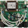
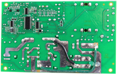
Visual Inspection
One of the most important things you can do when you are looking for a replacement is to visually inspect the PCB that you have versus the picture online of the replacement you are considering. They need to look the same even if there are the differences in firmware revisions or OEM part numbers, you should be visually replacing a PCB that looks like the one you have.
Configuring a replacement Hot Tub Circuit Board (PCB)
When you get a new PCB, you are more than likely going to need to configure it. Most PCBs have a number of different modes and setups that the can operate in. For this, you will need to manual or spec sheet to guide you.
For things like DIP switches, most of the time you can copy the settings from your original circuit board. You are looking for things like setting the voltage as a lot of PCBs can be configured to run on both 115V and 230V.
You may need to move jumpers or even wires to configure voltages – the key here is that you read the schematic and don’t expect the PCB to just work out of the box – it usually doesn’t.
Troubleshooting a Hot Tub Circuit Board (PCB)
Here are some common things you will see when you replace a PCB on a hot tub.
You press the buttons on the topside control and they don’t control the right parts (pumps or blower etc) – this is a mode configuration thing and you will either need to change some DIP switches on the PCB or an internal or low level programming mode on the topside control. Check the manual for how to do this.
You turn on the hot tub and it trips the breaker – it is not common for a new PCB to fail out of the box (I have not seen one yet!) However, a common mistake is that the voltage has not been set correctly. If it is set for 115V and then you try and turn it on, the current draw will be a lot more (twice) than expected and the breaker will trip.
To check this, unplug all of your kit – heater, pumps, blower and then turn on the PCB. If it trips with nothing plugged in, usually the voltage is incorrectly set and what is happening is that live current is being sent to the ground – because you have 4 wires into the PCB rather than 3. Current on the ground loop causes the trip. Check the settings to make sure it is configures for 230V.
It might not trip until you physically turn on a pump or a blower. As mentioned, if the pack is set to 115V and your pump is meant for 230V, it will draw twice the current at half the voltage and trip your breaker. Check the manual for info on how to set the voltage.
| Hpart # | 59-138-3000 |
|---|---|
| Brand | Balboa Water Group |
Related products
$481.65
Hydro-Quip Spa Controls
Hydro-Quip Outdoor Series 5.5kW 230V Flow Thru Heater 26-0053-F-M7-KS
$185.33
Out of stock
Balboa Topside Controls (Overlays)
$215.80
Gecko Spa Pack Controls
Gecko in.yt Spa Control 4.0kW Flow Thru Heater 0611-221031-361
$752.14
Watkins Topside Controls
$142.03
Out of stock
Master Spa Circuit Boards
Master Spas® MS2000 Replacement Circuit Board — X801080 — Balboa® 52959
$603.80
Gecko Spa Pack Controls
$343.01
Out of stock
Gecko Heating
$112.64