
Master Spas® MS2000 Replacement Circuit Board — X801080 — Balboa® 52959
$603.80
Circuit Board, Master Spa, MS 2000 PC
Out of stock
Want to be notified when this product is back in stock?
Fast dispatch
Order in
--:--:--
for shipping today
🛁 Master Spas® MS2000 Replacement Circuit Board — X801080 — Balboa® 52959
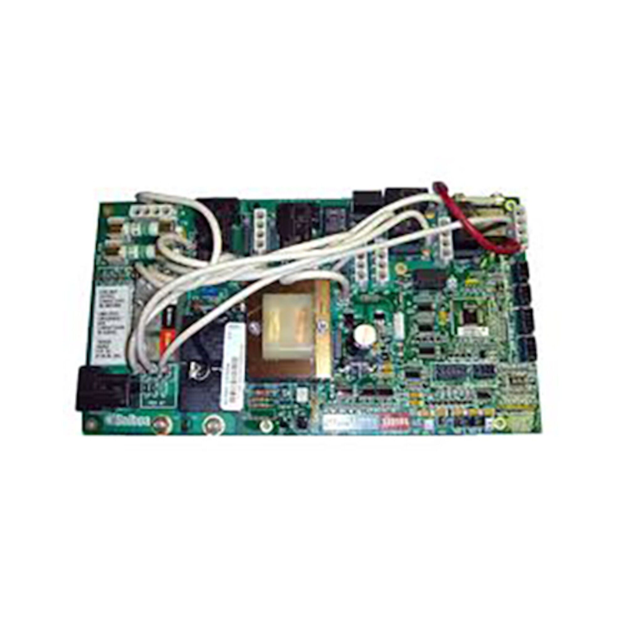
Genuine OEM replacement circuit board for Master Spas® and Down East Spas® equipped with the MS2000 control system — Molex style connector.
⚠️ IMPORTANT — PLEASE READ BEFORE ORDERING
- Confirm by part number, not appearance. Do not order this board based on visual appearance alone. Several boards look identical but carry different chip software. The identifiers for this board are X801080 (Master Spa part number) and MS2000 (chip designation). Locate the chip sticker near the center of your existing board and confirm it reads MS2000 before ordering.
- DIP switch configuration is required after installation. This board is not plug-and-play — correct voltage setup, component wire configuration, and DIP switch settings must be applied. Refer to the wiring schematics on the back of the spa pack cover.
📋 Product Overview
The Master Spas® X801080 is the OEM replacement circuit board for spa control systems using the MS2000 platform. Manufactured by Balboa Water Group (Balboa part number 52959, control box number 52958-01), this board is used in Master Spas and Down East Spas models equipped with the MS2000 control system. It uses a Molex style plug connector.
The MS2000 board is a genuine OEM part produced by Balboa for Master Spas, and can be identified on the board by the MS2000 chip designation or the Balboa part number 52959.
✨ Key Features
✅ Genuine OEM replacement circuit board — manufactured by Balboa for Master Spas®
✅ Master Spa Part Number: X801080
✅ Balboa Part Number: 52959 | Control box number: 52958-01
✅ Chip designation: MS2000
✅ Molex style plug connector
✅ For Master Spas® and Down East Spas® with MS2000 control system
✅ Factory-new — never installed
✅ Manufacturer’s warranty included
🔧 Technical Specifications
| Specification | Value |
|---|---|
| Master Spa Part Number | X801080 |
| Balboa Part Number | 52959 |
| Control Box Number | 52958-01 |
| Chip Designation | MS2000 |
| Connector Type | Molex style plug |
| Applicable Brand(s) | Master Spas® / Down East Spas® |
| System | MS2000 control system |
| Manufacturer | Balboa Water Group (for Master Spas) |
| Board Type | New — genuine OEM |
| Returns | Non-returnable |
| Warranty | Manufacturer’s warranty |
⚠️ For voltage, amperage, heater output, pump configuration, and breaker specifications for your specific spa, refer to the wiring diagram and rating label on the back of your spa pack cover or the MS2000 system documentation.
🔗 Compatibility Guide
Applicable Systems:
This board is for Master Spas® and Down East Spas® models equipped with the MS2000 control system. The board can be identified by the MS2000 chip sticker near the center of the existing circuit board, or by Balboa number 52959 printed on the board itself.
How to Confirm Compatibility:
- Locate the chip sticker near the center of your existing board — confirm it reads MS2000
- Or locate the Balboa 5-digit number on the board — confirm it reads 52959
- Confirm the existing board uses a Molex style plug connector
- Confirm the control box number is 52958-01
⚠️ Contact Parts4Tubs with your spa’s model, year, and existing board’s chip number or part number if you are uncertain whether this board is correct for your spa.
Replaces These Part Numbers:
| Part Number | Notes |
|---|---|
| X801080 | Master Spa PN — this board |
| 52959 | Balboa board PN |
| 52958-01 | Balboa control box PN |
🛠️ Installation Requirements
⚠️ Installation must be performed by a licensed electrician in compliance with NEC and all applicable local codes.
Pre-Installation Checklist:
- [ ] Confirm chip reads MS2000 or Balboa number 52959 on existing board
- [ ] Confirm Molex style plug connector on existing board
- [ ] Obtain the wiring schematic from the back of the spa pack cover before starting
- [ ] Photograph all wiring connections and DIP switch positions before removal
- [ ] Disconnect all power at the GFCI breaker or service disconnect
- [ ] Allow capacitors to discharge before handling the board
Electrical Requirements:
| Requirement | Specification |
|---|---|
| GFCI | Class A GFCI required — NEC Article 680 |
| Ground & Bonding | Required — NEC Article 680 |
| Dedicated Circuit | Required |
| Disconnect Box | Within line of sight of spa, at least 5 ft away |
| Voltage | Refer to spa pack wiring diagram and rating label |
| Wire Type | Copper conductors only |
⚠️ Safety Warnings
- ⚠️ ALWAYS disconnect all power before circuit board work
- ⚠️ Licensed electrician installation required; NEC Article 680 compliance mandatory
- ⚠️ GFCI required; grounding and bonding required per NEC Article 680
- ⚠️ Do not order based on appearance — confirm chip reads MS2000 or Balboa PN 52959
- ⚠️ DIP switch and voltage configuration required — refer to wiring schematic on spa pack cover
- ⚠️ Damage from incorrect installation is NOT covered under warranty
❓ Frequently Asked Questions
Q: How do I confirm this is the correct board for my spa? A: Look for the chip sticker near the center of your existing circuit board — it should read MS2000. You can also look for the Balboa number 52959 printed directly on the board. If you find either of these numbers, the X801080 is your correct replacement. If uncertain, contact Parts4Tubs with your spa’s model, year, and the numbers from your existing board.
Q: Is this board for Master Spas or Down East Spas? A: Both. The MS2000 platform (Balboa 52959) was used in Master Spas and in Down East Spas models equipped with the MS2000 control system.
Q: Where can I find the wiring schematic for installation? A: The wiring schematic is typically printed on a label affixed to the back of the spa pack cover (the metal or plastic cover of the control box). This is the primary reference for voltage setup, DIP switch configuration, and component wiring.
Q: Does this board work straight out of the box? A: No. Circuit boards are not plug-and-play. After installation you will need to set the correct component voltage by repositioning wires, and configure the DIP switches correctly for your spa’s equipment. Refer to the wiring diagram on the spa pack cover for the exact settings.
Q: What warranty is included? A: This board comes with the manufacturer’s warranty (Master Spas / Balboa). Circuit boards are non-returnable — once purchased and installed, they can only be exchanged under warranty if faulty. Damage from incorrect installation or improper configuration is not covered.
✅ Why Choose the Master Spas® X801080 (Balboa® 52959)
✅ Genuine OEM circuit board — manufactured by Balboa for Master Spas
✅ Correct MS2000 platform — chip and Balboa PN verifiable directly on the board
✅ Molex style connector — direct match for MS2000 control system
✅ For Master Spas and Down East Spas — both brands covered
✅ Factory-new — never installed
✅ Manufacturer’s warranty included
🤝 Why Buy from Parts4Tubs
✅ Fast US shipping
✅ Compatibility verification support — contact us with chip number before ordering if unsure
✅ Competitive pricing
🔌 Summary
The Master Spas® X801080 (Balboa® 52959, box 52958-01) is the genuine OEM replacement circuit board for Master Spas® and Down East Spas® equipped with the MS2000 control system. Manufactured by Balboa Water Group, it uses a Molex style plug connector and carries the MS2000 chip designation. Confirm compatibility by checking the chip sticker or Balboa number (52959) on your existing board before ordering. DIP switch and voltage configuration is required after installation — refer to the wiring schematic on the back of the spa pack cover. Non-returnable; manufacturer’s warranty included.
Finding and identifying a replacement Hot Tub Circuit Board (PCB)
If you are looking to replace a failed PCB on your Hot Tub’s spa pack, then quite often identifying the part that you need can be the hardest thing.
Firstly, you are looking for a model number on the actual circuit board itself. Having the model or serial of your hot tub is not going to help at this point, you need to find the number on the PCB itself.
Now, with certain brands of PCB, the number of the replacement PCB that you need is not going to match identically the one you are replacing. Why is that I hear you ask?
Well, normally, it is an updated version. This means that it might have updated firmware on the PCB or be a later revision. Normally, this means that the part number would be slightly different. This is usually indicated with a “12345678 -x” at the end of that part number where x indicated a firmware revision.
In some cases, there will be some following letters on the part number of the circuit board, “12345678 -x MAS” this can indicate that the PCB was used for an OEM meaning it was produced for a certain hot tub manufacturer and the letters identify the manufacturer.
This means if you source an original PCB, it will not have the letters, but will in most cases work just fine.
It can be confusing I know!
What if you can’t find a model number?
If you can’t find a model number on the PCB itself, then you need to look for a model number on the spa pack. Normally, there is a sticker on the outside of the spa pack that tells you the current ratings and input voltages etc and this will have a model number.
In general, most spa packs in the USA are manufactured by Balboa, Hydro-Quip, ACC or Gecko. I know I am generalising here, but if you have a spa pack that has the brand of your hot tub on, it will be an OEM so the key is identifying who made the original box.
From there, you can normally find an original PCB that you will be able to switch out.
For example, the Balboa VS (value series) is a very popular spa pack that has been used by multiple hot tub manufacturers under their own brand names. Whatever they have called it, strip it back and it is still a Balboa VS.
Visual Inspection
One of the most important things you can do when you are looking for a replacement is to visually inspect the PCB that you have versus the picture online of the replacement you are considering. They need to look the same even if there are the differences in firmware revisions or OEM part numbers, you should be visually replacing a PCB that looks like the one you have.
Configuring a replacement Hot Tub Circuit Board (PCB)
When you get a new PCB, you are more than likely going to need to configure it. Most PCBs have a number of different modes and setups that the can operate in. For this, you will need to manual or spec sheet to guide you.
For things like DIP switches, most of the time you can copy the settings from your original circuit board. You are looking for things like setting the voltage as a lot of PCBs can be configured to run on both 115V and 230V.
You may need to move jumpers or even wires to configure voltages – the key here is that you read the schematic and don’t expect the PCB to just work out of the box – it usually doesn’t.
Troubleshooting a Hot Tub Circuit Board (PCB)
Here are some common things you will see when you replace a PCB on a hot tub.
You press the buttons on the topside control and they don’t control the right parts (pumps or blower etc) – this is a mode configuration thing and you will either need to change some DIP switches on the PCB or an internal or low level programming mode on the topside control. Check the manual for how to do this.
You turn on the hot tub and it trips the breaker – it is not common for a new PCB to fail out of the box (I have not seen one yet!) However, a common mistake is that the voltage has not been set correctly. If it is set for 115V and then you try and turn it on, the current draw will be a lot more (twice) than expected and the breaker will trip.
To check this, unplug all of your kit – heater, pumps, blower and then turn on the PCB. If it trips with nothing plugged in, usually the voltage is incorrectly set and what is happening is that live current is being sent to the ground – because you have 4 wires into the PCB rather than 3. Current on the ground loop causes the trip. Check the settings to make sure it is configures for 230V.
It might not trip until you physically turn on a pump or a blower. As mentioned, if the pack is set to 115V and your pump is meant for 230V, it will draw twice the current at half the voltage and trip your breaker. Check the manual for info on how to set the voltage.
| Brand | Master Spa |
|---|
Related products
Hydro-Quip Spa Controls
Hydro-Quip Outdoor Series 5.5kW 230V Flow Thru Heater 26-0053-F-M7-KS
$185.33
Hydro-Quip Heaters
Hydro-Quip Outdoor Series 11kW 230V Flow Thru Heater 26-0054AF-M7-KS
$266.99
Gecko Spa Pack Controls
$343.01
Sundance Circuit Boards
$915.79

Balboa Circuit Boards
Balboa RS101 Spa Circuit Board — 456404-1 (Dream Maker / AquaRest OEM)
$373.96
Hydro-Quip Spa Controls
Hydro-Quip 6000 Series Spa Control Flow Thru Heater CS6200Y-U-WP
$672.91
$481.65
Watkins Topside Controls
$469.22