


Balboa BP501G1 Spa Circuit Board — G1351 (56944-01) — Multi-Setup 240V Control System
$349.00
27 in stock
Fast dispatch
Order in
--:--:--
for shipping today
🛠️ Balboa BP501G1 Spa Circuit Board — G1351 (56944-01) — Multi-Setup 240V Control System
Professional-grade replacement circuit board for reliable two-pump or circ-pump spa control.
📋 Product Overview
The Balboa BP501G1 spa circuit board (G1351, formerly 56944-01) is a genuine Balboa Water Group OEM PCB designed for the BP501G1 control system platform. This is one of Balboa’s most versatile and widely deployed circuit boards, capable of operating across six software-selectable setup configurations covering two-pump, blower, circulation pump, and single-pump spa arrangements.
The BP501G1 PCB manages up to two pumps, a blower, a circulation pump, spa lighting, an ozone generator, and an auxiliary/audio-video output — all configurable via DIP switches and jumpers to match a broad range of original equipment builds. It is compatible with the full range of Balboa TP-series and spaTouch™ touchscreen topside panels.
This board is a direct replacement for legacy Balboa BP501G1 system boards including part numbers 56488, 56488-02, and 56944-01. It is used across numerous hot tub brands including Cal Spas and Platinum Spas. Ships in factory default Setup #1; setup number, DIP switches, and voltage-select jumpers must be adjusted to match your existing board configuration before installation.
⚠️ Critical Limitation: A circulation pump cannot be used together with a 2-speed Pump 1 on this board. If your spa runs a 2-speed Pump 1 AND a circ pump simultaneously, the BP501G2 is required instead.
🌟 Key Features
✅ Genuine Balboa Water Group OEM PCB — Factory-quality board with chip BP501-X; not an aftermarket substitute
✅ Six Software Setups — Field-selectable configurations cover 2-speed pump, single-speed pump, circ pump, Pump 2, and blower combinations to match diverse original spa builds
✅ Dual-Pump Capability — Controls Pump 1 (2-speed or 1-speed) plus Pump 2 (1-speed) in Setups 1 & 2
✅ Blower Output — Dedicated 240V blower output (4A max) available in Setups 3 & 4
✅ Circulation Pump Support — Built-in circ pump output (2A max) with programmable filtration and polling cycles in Setups 2, 4, and 6
✅ 5.5kW or 4.0kW Heater Compatible — Supports both heater capacities depending on system part number
✅ Ozone Output — 240V ozone output slaved to heater pump (circ or P1 Low) for effective water treatment
✅ Broad Topside Compatibility — Works with Balboa TP200, TP400, TP500, TP600, TP700, TP740, TP800, TP900, and all spaTouch™ panel series
✅ AV / Clim8zone™ Output — Integrated 240V output for audio-video accessories and Clim8zone™ heat pump support (J47)
✅ CHROMAZON3™ Compatible — Supports Balboa’s LED color lighting system (shared 2A light output)
✅ bba™2 / bba™3 Bluetooth Amp Ready — Balboa Bluetooth module compatible via integrated TP700/TP800/TP900/spaTouch™ panels
✅ 1-Year Manufacturer Warranty — Backed by Balboa Water Group
✅ Made in the USA — Balboa Water Group, a Helios Technologies company
🔩 Technical Specifications
| Specification | Value |
|---|---|
| Current Balboa Part Number (MPN) | G1351 |
| Previous Part Number | 56944-01 |
| Legacy Part Number | 56488 / 56488-02 |
| Main PCBA Part Number | 56944-02 |
| Chip Number | BP501-X |
| Board Model | BP501G1 |
| Connector Type | 4-pin Molex |
| Board Dimensions | 11 in × 5 in |
| System PNs (5.5kW variants) | 56485-07 (800 Incoloy), 56486-07 (825 Incoloy), 56487-07 (Titanium) |
| System PN (4.0kW variant) | 56567-06 (800 Incoloy) |
| UL System Model (5.5kW) | BP501-BP501G1-BU |
| UL System Model (4.0kW) | BP501-BP501G1-BS |
| Software Version | V65.0 (M100_201) |
| Input Voltage (standard) | 240VAC / 50/60Hz |
| Service (standard 240V) | 48A, Class A GFCI-protected, 4-wire (Hot, Hot, Neutral, Ground) |
| Max Breaker (standard 240V) | 60A |
| Input Voltage (Setups 5 & 6 only) | 120V or 240VAC / 50/60Hz |
| Service (120V, wall-mount GFCI) | 16A, 20A GFCI/breaker |
| Service (120V, GFCI cord) | 12A max |
| Max Breaker (120V) | 20A |
| Pump 1 Output | 240VAC, 2-Speed (Setups 1,3,5) or 1-Speed (Setups 2,4,6), 12A max |
| Pump 2 Output | 240VAC, 1-Speed, 12A max — Setups 1 & 2 |
| Blower Output | 240VAC, 1-Speed, 4A max — Setups 3 & 4 |
| Circ Pump Output | 240VAC, 1-Speed, 2A max — Setups 2, 4, 6 |
| Ozone Output | 240VAC, 0.5A max |
| Spa Light Output | 10VAC, 2A max (shared with CHROMAZON3™) |
| AV / Clim8zone™ Output (J47) | 240VAC, 2A (AV) + 8A (C8Z) max |
| Heater Output (5.5kW systems) | 5.5kW @ 240VAC |
| Heater Output (4.0kW systems) | 4.0kW @ 240VAC |
| Heater Output (120V, Setups 5 & 6) | 1.25kW @ 120VAC |
| Number of Software Setups | 6 |
| DIP Switches | 6-position Switchbank S1 |
| Fuse F3 | 10A 250V (PN 26904) |
| Fuse F4 | 2A 250V (PN 26307) |
| Fuse F5 | 30A 250V (PN 30136) |
| Fuse F6 | 0.5A 250V (PN 26905) |
| Fuse F7 | 2A 250V (PN 26307) |
| Wire Type | Copper conductors only |
| Minimum Wire Gauge | #6 AWG, 90°C-rated |
| TB1 Torque | 27–30 in. lbs. |
| Heater Connection Torque | 30–35 in. lbs. |
| Hi-Range Temp (adjustable) | 80°F–104°F (26.7°C–40°C) |
| Lo-Range Temp (adjustable) | 50°F–99°F (10°C–37.2°C) |
| Freeze Threshold | 44°F (6.7°C) |
| Warranty | 1 year (manufacturer) |
⚠️ Board ships in factory default Setup #1. Setup number, DIP switches, and voltage-select jumpers must be adjusted to match your original board’s configuration prior to installation.
ℹ️ US Voltage Note: Standard residential 240V/60Hz service. Setups 5 & 6 only support optional 120V operation with appropriate GFCI protection.
✅ Compatibility Guide
Compatible Topside Panels:
| Panel Series | Version Required | Notes |
|---|---|---|
| spaTouch™ Mini | Any | Any version for Clim8zone™ support (v1.0+) |
| spaTouch™ 3 | Any | v3.2+ for Clim8zone™ support |
| spaTouch™ 2 | Any | v2.19+ for CHROMAZON3™; v2.36+ for Clim8zone™ |
| Icon spaTouch™ | Any | v3.36+ for bba™2 fully integrated |
| Menued spaTouch™ | Any | v2.8+ for bba™2 integrated |
| TP900 | v3.1 and later | v3.13+ for bba™ |
| TP800 | v3.1 and later | v3.13+ for bba™; v4.11+ for bba™2 integrated |
| TP700 / TP740 | Any | v1.27+ for Clim8zone™ support |
| TP600 | v2.7 and later | v2.12+ for bba™/bba™2 On/Off via menu |
| TP500 | Any | All versions |
| TP400T US | v2.7 and later | v2.12+ for bba™/bba™2 On/Off via menu |
| TP400W US | v2.7 and later | v2.12+ for bba™/bba™2 On/Off via menu |
| TP200T | Any | All versions |
| TP200W | Any | All versions |
Replaces the Following Part Numbers:
| Legacy Part Number | Description |
|---|---|
| 56944-01 | Balboa BP501G1 PCB (previous version) |
| 56488 | Balboa BP501G1 PCB (legacy) |
| 56488-02 | Balboa BP501G1 PCB (legacy) |
| 56485-03 through 56485-07 | BP501G1 System, 5.5kW 800 Incoloy (various revisions) |
| 56486-03 through 56486-07 | BP501G1 System, 5.5kW 825 Incoloy (various revisions) |
| 56487-03 through 56487-07 | BP501G1 System, 5.5kW Titanium (various revisions) |
| 56567-01 through 56567-06 | BP501G1 System, 4.0kW 800 Incoloy (various revisions) |
⚠️ Always verify your existing board’s chip number and part number before ordering. Do not order a circuit board based on appearance — many boards look similar but have different software.
🎛️ Board Functions & Setup Configurations
Software Setup Reference Table:
| Setup # | Circ Pump | Pump 1 | Pump 2 | Blower | Temp Scale |
|---|---|---|---|---|---|
| 1 (default) | None | 2-Speed | 1-Speed | None | °F |
| 2 | Prog. Filtration + Polling | 1-Speed | 1-Speed | None | °F |
| 3 | None | 2-Speed | None | 1-Speed | °F |
| 4 | Prog. Filtration + Polling | 1-Speed | None | 1-Speed | °F |
| 5 | None | 2-Speed | None | None | °F |
| 6 | Prog. Filtration + Polling | 1-Speed | None | None | °F |
⚠️ In Setups 1, 3, and 5 (no circ pump), Pump 1 acts as the heater pump. ⚠️ In Setups 2, 4, and 6 (with circ pump), the circ pump acts as the heater pump.
Pump Outputs:
| Output | Connector | Voltage | Max Amps | Timer |
|---|---|---|---|---|
| Pump 1 (2-speed) | J8 | 240VAC | 12A max | 15 min (30 min P1 Low, non-circ) |
| Pump 2 (1-speed) | J14 | 240VAC | 12A max | 15 min |
| Blower (1-speed) | J14 | 240VAC | 4A max | 15 min |
| Circ Pump | J21 | 240VAC | 2A max | Programmable |
Heater Control:
| Feature | Specification |
|---|---|
| Heater Type | Flow-through (Plug+Click connection) |
| Max Output (5.5kW system) | 5.5kW @ 240VAC |
| Max Output (4.0kW system) | 4.0kW @ 240VAC |
| Max Output (120V, Setups 5 & 6) | 1.25kW @ 120VAC |
| Heater Connector | J46 |
| Hi-Range Set Temp | 80°F–104°F |
| Lo-Range Set Temp | 50°F–99°F |
| Freeze Threshold | 44°F (6.7°C) — rotating pump activation |
| Cooldown (electric heater) | 1 minute (DIP Switch 4 OFF) |
| Cooldown (gas heater) | 5 minutes (DIP Switch 4 ON) |
Additional Outputs:
| Function | Connector | Rating | Notes |
|---|---|---|---|
| Ozone | J24 | 240VAC, 0.5A max | Slaved to circ pump (circ setups) or P1 Low (non-circ) |
| Spa Light / CHROMAZON3™ | J15 | 10VAC, 2A max (shared) | 240-min timer |
| AV + Clim8zone™ | J47 | 240VAC, 2A + 8A max | Splitter PN 22934 if two devices needed |
| Aux Panel Bank 1 | J5 | — | AX10, AX20, AX40 auxiliary panels |
DIP Switch Functions (Switchbank S1):
| Switch | OFF Position | ON Position |
|---|---|---|
| 1 | Test Mode OFF (normal) | Test Mode ON — service only |
| 2 | No heat with any HS pump/blower | Heat with 1 high-speed pump running |
| 3 | See Switch 2 | Heat with 2 HS pumps (or 1 HS + blower) running |
| 4 | 1-min cooldown (electric heater) | 5-min cooldown (gas heater) |
| 5 | Special Amperage Rule A | Special Amperage Rule B |
| 6 | Normal operation | Memory Reset (power-up) |
⚠️ Switch 6 must be set to OFF upon final installation.
Key Jumpers:
| Jumper | Function |
|---|---|
| J44 | 230V config: center 2 pins; 115V config: left + right 2 pins (when neutral wire used) |
| J29 | Heater Disable Switch input; if shorted, heater will not run |
| J25, J26, J27 | Heater type settings — factory configured, do NOT change |
| J109 | GFCI Test/Trip Enable/Disable |
| J30 | Do Not Use |
⚙️ Installation Requirements
⚠️ IMPORTANT: Installation must be performed by a licensed electrician in full compliance with NEC (National Electrical Code) and all applicable local codes.
Pre-Installation Checklist:
- [ ] Confirm chip number and part number of existing board before ordering
- [ ] Note your existing software Setup # (written on label inside system lid)
- [ ] Disconnect all power at the GFCI breaker or disconnect box
- [ ] Photograph all wiring, connector positions, DIP switch settings, and jumper positions before removal
- [ ] Allow capacitors to discharge — wait at least 5 minutes after power-off
- [ ] Disconnect J52 slip terminal (green wires) before any HiPot test
- [ ] Note: board ships in Setup #1 — DIP switches, voltage-select jumpers, and setup must be adjusted before power-up
Electrical Requirements (Standard 240V Configuration):
| Requirement | Specification |
|---|---|
| Supply Voltage | 240VAC / 60Hz |
| Service | 48A, 4-wire (Hot, Hot, Neutral, Ground) |
| Circuit Breaker | 60A maximum |
| GFCI Protection | Class A GFCI required — NEC Article 680 |
| Ground & Bonding | Equipment grounding and bonding required — NEC Article 680 |
| Dedicated Circuit | Required |
| Disconnect Box | Required within line of sight of spa, min. 5 ft from inside spa walls (NEC) |
| Wire Type | Copper conductors ONLY |
| Min. Wire Gauge | #6 AWG, 90°C-rated |
| TB1 Torque | 27–30 in. lbs. |
| Heater Connection Torque | 30–35 in. lbs. |
Electrical Requirements (120V Option — Setups 5 & 6 Only):
| Requirement | Specification |
|---|---|
| Supply Voltage | 120VAC / 60Hz |
| Service (wall-mount GFCI) | 16A, 20A GFCI/breaker |
| Service (GFCI cord) | 12A max |
| Pump 1, Circ Pump, Ozone | Must be wired to 120VAC — move wires at J50 and J51 to Area 1 (Neutral) |
| DIP Switches 2 & 3 | Must be set to OFF when system is configured for 120VAC |
| Clim8zone™ | Cannot be used in 120VAC configuration |
Key Board Connectors:
| Connector | Function |
|---|---|
| TB1 | Main power terminal block |
| J8 | Pump 1 (2-speed or 1-speed) |
| J14 | Pump 2 (1-speed) or Blower |
| J15 | Spa Light / CHROMAZON3™ (10V) |
| J21 | Circ Pump |
| J24 | Ozone |
| J46 | Heater (240V, Plug+Click) |
| J47 | AV + Clim8zone™ |
| J50, J51 | P1 / Circ / Ozone voltage selection |
| J5 | Aux Panel connection (Bank 1) |
| J33 / J45 | Main topside panel connections |
| J52 | Disconnect before HiPot test |
| S1 | 6-position DIP switchbank |
💡 Tip: Using a permanent marker, write the Setup number on the label inside the system lid. This is critical information for any future service technician.
Setup Change Procedure (TP600/TP400 Panels):
- Enter Test Mode: turn DIP Switch 1 ON while system is running
- During Priming Mode, press any Temperature button once to exit Priming Mode
- Press: Warm, Light, Warm, Warm, Warm, Warm — continue pressing Warm until desired Setup Number appears
- Press Light once to confirm — system resets to new Setup
- Turn DIP Switch 1 OFF to exit Test Mode
Memory Reset Procedure:
- Set DIP Switch 6 to ON at power-up to restore factory settings
- ⚠️ Switch 6 must be returned to OFF upon final installation
🛡️ Safety Warnings
Electrical Safety:
- ⚠️ ALWAYS disconnect all power before performing any board work — high-voltage shock hazard
- ⚠️ Licensed electrician installation required — NEC compliance mandatory
- ⚠️ Class A GFCI protection required per NEC Article 680
- ⚠️ Equipment grounding AND bonding mandatory per NEC Article 680
- ⚠️ Verify supply voltage matches board configuration before connecting
- ⚠️ Use copper conductors only — minimum #6 AWG, 90°C-rated
- ⚠️ Do not exceed TB1 torque (27–30 in.lbs.) or heater connection torque (30–35 in.lbs.)
- ⚠️ Disconnect J52 slip terminal (green wires) before performing any HiPot testing
DIP Switch & Configuration Safety:
- ⚠️ Setting DIP switches or jumpers incorrectly may cause abnormal system behavior or component damage
- ⚠️ Switch 6 (Memory Reset) must be OFF upon final installation
- ⚠️ Do NOT change factory-configured jumpers J25, J26, J27 (heater type settings)
- ⚠️ In 120VAC configuration (Setups 5 & 6 only), Pump 1, Circ, and Ozone must all be wired to 120VAC — move J50 and J51 to Area 1 (Neutral)
- ⚠️ DIP Switches 2 & 3 must be OFF when configured for 120VAC
Critical System Limitation:
- ⚠️ A circulation pump cannot be used together with a 2-speed Pump 1 in this system. If your spa requires this combination, the BP501G2 board is required.
Water & Component Safety:
- ⚠️ Inspect all enclosure seals before installation — no water ingress permitted
- ⚠️ Never handle electrical components with wet hands
- ⚠️ Test Mode (DIP Switch 1 ON) exposes high voltage — for licensed service technicians only
Post-Installation:
- ⚠️ Verify all safety features before spa use
- ⚠️ Test GFCI operation after installation
- ⚠️ Check for error codes and monitor board on first startup
🔍 Error Codes & Diagnostics
Power-Up Sequence:
On startup, the spa enters Priming Mode automatically. The display will show “RUN PMPS PURG AIR” during pump purge. Priming Mode exits automatically after 4 minutes, or can be manually exited by pressing a Temperature button.
Test Mode Indicators:
| Display | Meaning |
|---|---|
| °T after temperature (e.g., “100T”) | System is in Test Mode (DIP Switch 1 ON) |
| “°F” or “°C” after temperature | Normal operating mode |
| “J29” on display at power-up | J29 heater disable connector is shorted — check for external switch closure or short at J29 |
| “S-01”, “S-02” etc. | Software Setup selection screen (during Test Mode setup change) |
Fault Log: Accessible via the Test Menu on TP800/TP900/spaTouch™ panels. Records system faults for service diagnosis.
Filter Reminders (default schedule):
| Reminder | Default Period |
|---|---|
| Clean Filter | 30 days |
| Test GFCI | 65 days |
| Drain Water | 100 days |
| Change Filter | 365 days |
⚠️ For complete BP501 error code documentation, refer to the Balboa BP501G1 Tech Sheet (see Downloads) or contact Parts4Tubs technical support.
🎯 Ideal Applications
| Application | Suitability | Notes |
|---|---|---|
| ♨️ Two-pump spas (P1 + P2, no circ) | ✅ Setup 1 — direct application | P1 is heater pump |
| ♨️ Two-pump spas (P1 + P2, with circ) | ✅ Setup 2 — circ as heater pump | Circ pump required |
| ♨️ Single-pump + blower spas | ✅ Setups 3 & 4 | With or without circ |
| ♨️ Single-pump only spas | ✅ Setups 5 & 6 | Optional 120V operation |
| ♨️ Cal Spas (BP501G1 equipped) | ✅ Compatible | OEM board for select Cal Spas models |
| ♨️ Platinum Spas | ✅ Compatible | Replaces CTR-BP501G1 |
| ♨️ Any BP501G1 system spa | ✅ Direct PCB replacement | Confirm setup, chip number |
This board is NOT suitable for:
- Spas requiring a 2-speed Pump 1 combined with a circ pump simultaneously — use BP501G2 instead
- Export 50Hz CE-market spas — this is a UL/North American 60Hz board
❓ Frequently Asked Questions
Q: How do I know which Setup my spa uses? A: Check the label inside your system enclosure lid — the Setup number should be written there. If not, check the wiring diagram attached to the inside of the spa pack cover, or contact Parts4Tubs with your spa make, model, and control system part number.
Q: My spa has a 2-speed pump and a circ pump. Will this board work? A: No. The BP501G1 cannot run a 2-speed Pump 1 together with a circulation pump. Your spa requires the BP501G2 instead. Contact Parts4Tubs for assistance.
Q: Is this an OEM or aftermarket board? A: This is a genuine Balboa Water Group OEM circuit board (G1351 / 56944-01).
Q: The board ships in Setup #1 — do I need to change it? A: Yes, if your original board was configured in a different Setup. You must adjust the Setup number, DIP switches, and voltage-select jumpers to match your original board’s configuration. Refer to the tech sheet and wiring diagram inside your spa pack cover. If you are unsure, contact Parts4Tubs for assistance.
Q: Can this board run on 120V? A: Yes, but only in Setup 5 or Setup 6, and only with appropriate 120V GFCI protection. In 120V mode, the heater outputs 1.25kW. Pump 1, circ pump, and ozone must all be rewired to 120VAC (J50 and J51 to Area 1). DIP Switches 2 and 3 must be OFF. Note that Clim8zone™ cannot be used in 120VAC configuration.
Q: Do I need a licensed electrician to install this? A: Yes. NEC Article 680 and most local codes require a licensed electrician for all hot tub electrical work. A permit may also be required in your jurisdiction.
Q: Which topside panel works with this board? A: The BP501G1 is compatible with a wide range of Balboa panels including TP200, TP400, TP500, TP600, TP700, TP740, TP800, TP900, and the full spaTouch™ line. See the Compatibility Guide section for version requirements. Contact Parts4Tubs if you are unsure about your specific panel.
Q: What warranty is included? A: 1-year manufacturer warranty from Balboa Water Group. Contact Parts4Tubs for complete terms.
Q: What if the heater won’t run after installation? A: Check that J29 is not shorted — a shorted J29 disables the heater. If “J29” appears on the display at startup, inspect the heater disable connector. Also verify DIP switch settings and ensure Switch 6 is in the OFF position.
📑 Downloads & Resources
📄 Balboa BP501G1 Tech Sheet — Current Version (Official PDF) — Full wiring diagrams, DIP switch settings, setup table, connector layout, panel configurations, and configuration options
⭐ Why Choose the Balboa BP501G1 PCB (G1351)
✅ Genuine OEM Balboa Water Group board — same component as original equipment; no compatibility guesswork
✅ Six field-selectable software setups — one board covers a broad range of pump and blower configurations
✅ Broadest topside panel compatibility — works with all Balboa TP and spaTouch™ panel families
✅ 5.5kW and 4.0kW heater variants available — select the right capacity for your system
✅ Advanced feature support — CHROMAZON3™, bba™2/bba™3 Bluetooth, Clim8zone™ heat pump ready
✅ 1-year manufacturer warranty — factory-backed coverage
✅ Parts4Tubs expert support — our team can help verify your setup configuration and confirm compatibility
✅ Made in the USA — Balboa Water Group, a Helios Technologies company
🛒 Why Buy from Parts4Tubs
✅ Fast US shipping
✅ Expert technical advice from spa specialists
✅ Competitive pricing
✅ Full warranty support
✅ Easy returns within 30 days
✅ Compatible parts and accessories available
✅ Help identifying the correct Setup, DIP switch configuration, and compatible topside panels
💡 Summary
The Balboa BP501G1 PCB (G1351) is a genuine OEM replacement circuit board for the BP501G1 control system platform. With six software-selectable setup configurations, it covers two-pump, blower, circulation pump, and single-pump spa arrangements operating on 240V (or 120V in Setups 5 & 6). It supports heaters up to 5.5kW and is compatible with every Balboa TP-series and spaTouch™ topside panel. If your spa runs a 2-speed Pump 1 without a circ pump, or a 1-speed Pump 1 with a circ pump, this board is the right choice — order with confidence and restore your spa to full operation.

Parts4Tubs is proud to be a Balboa Authorized Online Seller - make sure you only buy genuine Balboa parts from trusted sources.
Parts4Tubs is proud to be a Balboa Authorized Online Seller - make sure you only buy genuine Balboa parts from trusted sources.
Finding and identifying a replacement Hot Tub Circuit Board (PCB)
If you are looking to replace a failed PCB on your Hot Tub’s spa pack, then quite often identifying the part that you need can be the hardest thing.
Firstly, you are looking for a model number on the actual circuit board itself. Having the model or serial of your hot tub is not going to help at this point, you need to find the number on the PCB itself.
Now, with certain brands of PCB, the number of the replacement PCB that you need is not going to match identically the one you are replacing. Why is that I hear you ask?
Well, normally, it is an updated version. This means that it might have updated firmware on the PCB or be a later revision. Normally, this means that the part number would be slightly different. This is usually indicated with a “12345678 -x” at the end of that part number where x indicated a firmware revision.
In some cases, there will be some following letters on the part number of the circuit board, “12345678 -x MAS” this can indicate that the PCB was used for an OEM meaning it was produced for a certain hot tub manufacturer and the letters identify the manufacturer.
This means if you source an original PCB, it will not have the letters, but will in most cases work just fine.
It can be confusing I know!
What if you can’t find a model number?
If you can’t find a model number on the PCB itself, then you need to look for a model number on the spa pack. Normally, there is a sticker on the outside of the spa pack that tells you the current ratings and input voltages etc and this will have a model number.
In general, most spa packs in the USA are manufactured by Balboa, Hydro-Quip, ACC or Gecko. I know I am generalising here, but if you have a spa pack that has the brand of your hot tub on, it will be an OEM so the key is identifying who made the original box.
From there, you can normally find an original PCB that you will be able to switch out.
For example, the Balboa VS (value series) is a very popular spa pack that has been used by multiple hot tub manufacturers under their own brand names. Whatever they have called it, strip it back and it is still a Balboa VS.
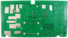
Visual Inspection
One of the most important things you can do when you are looking for a replacement is to visually inspect the PCB that you have versus the picture online of the replacement you are considering. They need to look the same even if there are the differences in firmware revisions or OEM part numbers, you should be visually replacing a PCB that looks like the one you have.
Configuring a replacement Hot Tub Circuit Board (PCB)
When you get a new PCB, you are more than likely going to need to configure it. Most PCBs have a number of different modes and setups that the can operate in. For this, you will need to manual or spec sheet to guide you.
For things like DIP switches, most of the time you can copy the settings from your original circuit board. You are looking for things like setting the voltage as a lot of PCBs can be configured to run on both 115V and 230V.
You may need to move jumpers or even wires to configure voltages – the key here is that you read the schematic and don’t expect the PCB to just work out of the box – it usually doesn’t.
Troubleshooting a Hot Tub Circuit Board (PCB)
Here are some common things you will see when you replace a PCB on a hot tub.
You press the buttons on the topside control and they don’t control the right parts (pumps or blower etc) – this is a mode configuration thing and you will either need to change some DIP switches on the PCB or an internal or low level programming mode on the topside control. Check the manual for how to do this.
You turn on the hot tub and it trips the breaker – it is not common for a new PCB to fail out of the box (I have not seen one yet!) However, a common mistake is that the voltage has not been set correctly. If it is set for 115V and then you try and turn it on, the current draw will be a lot more (twice) than expected and the breaker will trip.
To check this, unplug all of your kit – heater, pumps, blower and then turn on the PCB. If it trips with nothing plugged in, usually the voltage is incorrectly set and what is happening is that live current is being sent to the ground – because you have 4 wires into the PCB rather than 3. Current on the ground loop causes the trip. Check the settings to make sure it is configures for 230V.
It might not trip until you physically turn on a pump or a blower. As mentioned, if the pack is set to 115V and your pump is meant for 230V, it will draw twice the current at half the voltage and trip your breaker. Check the manual for info on how to set the voltage.
| Hpart # | 59-138-3141 |
|---|---|
| Brand | Balboa Water Group |
Related products
Watkins Topside Controls
$469.22
Out of stock
Gecko Heating
$94.51
Spa Accessories
$310.69
Sundance Circuit Boards
⚙️ Sundance® / Jacuzzi® 6600-390 880 NT System Spa Circuit Board (2-Pump with PermaClear®)
$966.39
Out of stock
Gecko Heating
$112.64
Gecko Spa Pack Controls
$343.01
Sundance Circuit Boards
$915.79
Gecko Spa Pack Controls
Gecko in.yt Spa Control 4.0kW Flow Thru Heater 0611-221031-361
$752.14