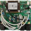


Balboa Genuine VS520SZ Spa Circuit Board — G1157 (55151-01) — Dual 2-Speed Pump 240V Serial Standard Control System
$349.00
17 in stock
🌊 Balboa Genuine VS520SZ Spa Circuit Board — G1157 (55151-01) — Dual 2-Speed Pump 240V Serial Standard Control System
Genuine current-production circuit board for Balboa VS520SZ spa control systems.
⚠️ IMPORTANT — PLEASE READ BEFORE ORDERING
- Includes Plug’n’click heater adapter PN 25696. This board ships with the Plug’n’click receptacle adapter. For older spas with a screw-terminal heater, adapter PN 25263 (60-138-1040) is also required. Removing the copper heater strap is REQUIRED — old-style copper straps arc and cause damage.
- 2-speed Pump 2 requires the X-P332 expander board (PN 55137 / G1920). The VS520SZ system is not designed to run a 2-speed Pump 2 without the expander board. Do not order this board if your spa does not use a 2-speed second pump.
- ⚠️ OZONE AND CIRC PUMP VOLTAGE MUST MATCH. The W2 wire sets voltage for both the ozone connector (J29) and the circ pump connector (J47). If the wrong voltage is selected, equipment on the circ pump connector can be damaged.
- Identify by chip number. The VS520SZ board carries chip VS520SZR1A. Do not order based on appearance alone.
- Circuit boards are non-returnable. Contact Parts4Tubs to verify compatibility before ordering.
- Plastic enclosure only. Not for metal spa pack enclosures.
📋 Product Overview
The Balboa Genuine VS520SZ circuit board (Current MPN G1157, Base PCBA PN 55151-01, Chip VS520SZR1A) is Balboa Water Group’s current-production PCB for the VS520SZ Serial Standard control system. Built on the VS500Z PCB platform (22972 Rev C or D), this board is designed for spas running two 2-speed pumps, a blower, ozone, AV/stereo, and a 5.5kW heater — all through a compact 8-position DIP switchbank and Serial Standard topside interface.
The VS520SZ is unique in the VS lineup: it requires the X-P332 expander board (PN 55137) to deliver the second 2-speed pump output, which is a built-in feature of this system, not an optional add-on. Adding a blower or 1-speed Pump 3 is possible via connector J17/26 (DIP A7 ON). The board connects to Serial Standard digital topside panels including the VL600, VL701, VL701S, and VL702S.
This board includes the Plug’n’click heater adapter (PN 25696) and has been used in Clearwater Spas and Cal Spas hot tubs, as well as any spa originally built around the Balboa VS520SZ spa pack.
✨ Key Features
✅ Genuine Balboa Water Group — Current MPN G1157 — latest-production board replacing all 55151 revisions
✅ Includes Plug’n’click heater adapter PN 25696 — no separate purchase needed for new-heater installations
✅ Eliminates copper strap arcing risk — Plug’n’click design replaces failure-prone copper strap connections
✅ Two-Speed Pump 1 — 240V main jet pump, high and low speed
✅ Two-Speed Pump 2 — 240V, requires X-P332 expander board (PN 55137 / G1920); built into system
✅ Blower or 1-Speed Pump 3 Option — via J17/26, enabled by DIP A7 ON
✅ Circulation Pump Output — 240V, optional, separate connector J47
✅ Ozone Generator Output — 120V or 240V field-selectable via W2 wire
✅ Spa Light Output — 12V at J12
✅ AV / Stereo Output — 240V AV (Stereo) at J4; always-hot
✅ 5.5kW Heater Support — 240V flow-through heater at full rated output
✅ Single 8-Position DIP Switchbank — simple configuration for pump, circ, and heater modes
✅ Persistent Memory (J43) — stores filter settings, set temperature, and heat mode without a battery
✅ Dolphin Remote Compatible — Full-Feature and Spa-Only Dolphin Remote (J20)
✅ VX20 and VX40S Aux Panel Support — 2-button and 4-button auxiliary panel compatible
✅ M7 Technology — no pressure switch or external sensors required
✅ 1-Year Manufacturer Warranty — backed by Balboa Water Group
✅ Made in the USA — Balboa Instruments, Inc.
⚙️ Technical Specifications
| Specification | Value |
|---|---|
| Current Balboa MPN | G1157 |
| Base PCBA PN | 55151-01 |
| PCB Part Number | VS500Z PN 22972 Rev C or D |
| Chip Number | VS520SZR1A |
| System PN | 56007-01 |
| System Model | VSP-VS520SZ-DCAH |
| Software Version | 43 |
| EPN | 2808 |
| SSID | 100 — 98 — 43 |
| Included Accessory | Plug’n’click adapter PN 25696 |
| Input Voltage | 240VAC / 60Hz |
| Service Required | GFCI-protected, 4-wire (Hot, Hot, Neutral, Ground) |
| Max Breaker Rating | 50A |
| Heater Output | 5.5kW @ 240VAC |
| Pump 1 Output | 240V, 2-Speed |
| Pump 2 Output | 240V, 2-Speed — requires X-P332 expander board (PN 55137 / G1920) |
| Blower / Pump 3 Output | via J17/26, DIP A7 ON — 1-speed (Blower or Pump 3) |
| Circ Pump Output | 240V or 120V, J47 — must match ozone voltage (W2) |
| Ozone Output | 120V or 240V at J29 via W2 — must match circ pump voltage |
| Spa Light Output | 12V at J12 |
| AV / Stereo Output | 240V at J4, always-hot (no relay) |
| DIP Switches | Single Switchbank A: 8 positions (A1–A10, select positions used) |
| Fuse (logic) | 0.3A 250V |
| Fuse | 20A 250V |
| Fuse | 3A 250V |
| Fuse (F5) | CLASS G 30A |
| TB1 Torque | 27–30 in. lbs. |
| Wire Type | Copper conductors only |
| Enclosure | Plastic spa pack enclosure ONLY — NOT for metal enclosure |
| Heater Connection | Plug’n’click (PN 25696 included); for older heater use adapter PN 25263; copper strap removal required |
| Warranty | 1 year (manufacturer) |
⚠️ Breaker note: Maximum 50A breaker — this differs from EL-series boards which allow 60A. Verify your existing breaker matches.
ℹ️ Heater wattage note: 5.5kW at 240VAC. At 120V input the heater outputs approximately 1/4 of the 240V wattage.
🔗 Compatibility Guide
⚠️ IDENTIFY BY CHIP NUMBER: The VS520SZ board chip is VS520SZR1A. Do not order by appearance — VS500Z-platform boards look similar but carry different software for different system configurations.
Compatible Topside Panels (Serial Standard):
| Panel | Description | Notes |
|---|---|---|
| 53189-01 | Serial Standard (base panel) | PDF-confirmed; Overlay PN 10430 |
| VL600 / VL600S | Serial Standard digital 6-button | Compatible — commonly used on VS520SZ systems |
| VL701 / VL701S | 7-button Serial Standard | ✅ Horizon recommended (58-138-3434) |
| VL702S | 7-button Serial Standard | ✅ Horizon recommended (58-138-3436) |
ℹ️ All Serial Standard panels connect to J1 on the main board.
Aux Panel Support:
| Aux Panel | Description |
|---|---|
| VX20 | 2-button aux panel — compatible per tech sheet |
| VX40S | 4-button aux panel — compatible per tech sheet |
⚠️ Note: When DIP A7 is ON (J17/26 enabled for Blower or Pump 3), the panel layout changes — button 7 becomes the J17/26 control. The panel button layout with A7 ON is not compatible with all panel configurations.
Required Expander Board — X-P332:
| Item | Part Number | Description |
|---|---|---|
| X-P332 Expander | 55137 / G1920 (59-138-3194) | Required for 2-speed Pump 2 — 2-relay, 30A fuse |
⚠️ The 2-speed Pump 2 output requires the X-P332 expander board. This is not optional — the VS520SZ system is designed around this expander. If your spa does not have a 2-speed second pump, this board may not be the correct one for your system.
Replaces / Cross-Reference Part Numbers:
| Part Number | Description |
|---|---|
| G1157 | Current Balboa MPN — this board |
| 55151-01 | Base PCBA PN (previous version without Plug’n’click) |
| 55151 | Base PCBA PN (all revisions) |
| 33-55151-K | Hydroquip catalog number |
| 33-0033B-K | Hydroquip alternate number |
| 9710-116 | OEM catalog number |
| VS520SZR | Chip-based cross-reference |
| CLR55151-01 | Clearwater Spas OEM part number |
| ELE09204311 / VS5020SZ | Cal Spas OEM part number |
Compatible Spa Brands / OEM Cross-References:
| Brand | OEM Part Number | Notes |
|---|---|---|
| Clearwater Spas | CLR55151-01 | ✅ Confirmed OEM variant |
| Cal Spas | ELE09204311 / VS5020SZ | ✅ Confirmed OEM |
| HydroQuip | 33-55151-K / 33-0033B-K | ✅ Confirmed catalog numbers |
⚠️ Coleman Spas note: Coleman used a VS520SZ-platform board (Balboa PN 56057) with a different, Coleman-specific chip (COLE2PDVR1A/COLE2PDVR1B). This is not interchangeable with the G1157. If your Coleman spa has chip COLE2PDVR1A or COLE2PDVR1B, contact Parts4Tubs — the G1157 is not a compatible replacement.
🎛️ Board Functions & Controls
Pump & Output Configuration:
| Output | Connector | Voltage | Notes |
|---|---|---|---|
| Pump 1 | J1 | 240V, 2-Speed | Main jet pump |
| Pump 2 | Via X-P332 | 240V, 2-Speed | Expander board required |
| Blower / Pump 3 | J17/26 | 240V, 1-Speed | A7 ON required |
| Circ Pump | J47 | Match W2 voltage | Voltage = ozone W2 setting |
| Ozone | J29 + W2 | 120V or 240V | W2: Red AC = 240V, White AC = 120V |
| Spa Light | J12 | 12V | Factory set — DO NOT MOVE J12 jumper |
| AV / Stereo | J4 | 240V | Always-hot, no relay |
| Heater | HTR1/HTR2 | 240V, 5.5kW | M7 sensors in heater assembly |
⚠️ CRITICAL: Ozone and Circ Pump Voltage Warning The W2 wire controls voltage for BOTH the ozone connector (J29) and the circ pump connector (J47). If W2 is set for 240V ozone but your circ pump is 120V, the circ pump will be damaged. Always confirm both devices match the W2 voltage setting.
DIP Switchbank A (8-Position — PDF-CONFIRMED):
| Switch | OFF Position | ON Position |
|---|---|---|
| A1 | Test Mode OFF (normal) | Test Mode ON — technician only |
| A2 + A10 | See Table 1 — heater/amp control | See Table 1 |
| A3 | N/A — must remain OFF | N/A — must remain OFF |
| A4 | Aux Freeze — must remain OFF | must remain OFF |
| A5 + A9 | See Circ Mode Table — pump speed and circ | See Circ Mode Table |
| A6 | 60Hz operation (US normal) | 50Hz operation |
| A7 | J17/26 Disabled — no Blower/Pump 3 | J17/26 Enabled — Blower or 1-speed Pump 3 |
| A8 | Temperature in Fahrenheit | Temperature in Celsius |
Table 1 — Heater Amp Draw (A2 + A10):
| A2 | A10 | Max Hi-Speed Pumps/Blower Before Heater Disables |
|---|---|---|
| OFF | OFF | 0 (heater off whenever any HS device runs) |
| ON | OFF | 1 |
| OFF | ON | 2 |
| ON | ON | 3 |
Circ Mode Table (A5 + A9):
| A5 | A9 | Circ Mode | Pump 1 Speed |
|---|---|---|---|
| OFF | OFF | Non-circ | 2-Speed |
| ON | OFF | Circ — acts like Pump 1 Low (filters/polls) | 1-Speed |
| OFF | ON | 24 Hr with 3°F shut-off | 1-Speed |
| ON | ON | 24 Hr with 3°F shut-off | 2-Speed |
Key Jumpers:
| Jumper | Function |
|---|---|
| J12 | Factory set — DO NOT MOVE. Pins 1–2 required for VS51x/VS52x/VS5xxS/VS5xxD software. Moving this jumper will prevent the board from operating correctly. |
| J43 | Persistent Memory: 2 pins covered = RESET; 1 pin only = Enabled (normal) |
| W2 | Ozone voltage: Red AC = 240V; White AC = 120V. Also sets circ pump (J47) voltage. |
Panel Button Layout (Serial Standard):
| Button | Assignment |
|---|---|
| 1 | Mode |
| 2 | Temp Up |
| 3 | Temp Down |
| 4 | Light |
| 5 | Pump 1 |
| 6 | Pump 2 |
| 7 | Unused (or J17/26 when A7 is ON) |
🔧 Installation Requirements
⚠️ Installation must be performed by a licensed electrician in compliance with NEC and all applicable local codes.
Pre-Installation Checklist:
- [ ] Confirm chip number is VS520SZR1A — check white label on existing board
- [ ] Confirm spa uses 2-speed Pump 2 (X-P332 expander required)
- [ ] Record all DIP switch positions before removal
- [ ] Record W2 ozone voltage setting — and confirm it matches circ pump voltage
- [ ] Disconnect all power at the GFCI breaker or disconnect box
- [ ] Photograph all wiring and connections before removal
- [ ] Allow capacitors to discharge — wait 5 minutes after power-off
- [ ] Confirm enclosure is plastic — not for metal enclosures
- [ ] Remove the copper heater strap — required, not optional
- [ ] If existing heater has screw terminals: install adapter PN 25263 (60-138-1040) before connecting to PN 25696 (included)
- [ ] Do NOT move J12 jumper — factory set position must not change
Electrical Requirements:
| Requirement | Specification |
|---|---|
| Supply Voltage | 240VAC / 60Hz |
| Service | 4-wire (Hot, Hot, Neutral, Ground) |
| Circuit Breaker | 50A maximum |
| GFCI Protection | Class A GFCI required — NEC Article 680 |
| Ground & Bonding | Required — NEC Article 680 |
| Dedicated Circuit | Required |
| Disconnect Box | Within line of sight of spa, at least 5 ft from spa walls (NEC) |
| Wire Type | Copper conductors ONLY |
| TB1 Torque | 27–30 in. lbs. |
Key Board Connectors:
| Connector | Function |
|---|---|
| TB1 | Main power (Hot/Black, Hot/Red, Neutral/White, Ground) |
| J1 | Pump 1 (2-Speed), Serial Standard panel |
| J2 | Secondary connections |
| J4 | AV / Stereo output (always-hot) |
| J12 | Spa Light (12V) — factory jumper, do not move |
| J17/26 | Blower or 1-speed Pump 3 (A7 ON required) |
| J20 | Dolphin Remote receiver |
| J29 | Ozone connector — voltage set by W2 |
| J43 | Persistent Memory jumper |
| J47 | Circ Pump connector — voltage = W2 setting |
| HTR1/HTR2 | Heater connections |
| SEN. A | Hi-limit sensor |
| SEN. B | Temperature sensor |
| VAC | Pressure/vacuum switch input |
| EXT. RLY | External relay |
| AUX. F | Aux freeze sensor |
| W1 | Pump 1 2-speed relay wire |
| W2 | Ozone/Circ Pump voltage selector |
| W3 | Secondary connections |
| W7 | Circ pump relay wire |
| X-P332 connection | 2-speed Pump 2 via X-P332 expander board |
⚠️ Persistent Memory Reset (REQUIRED after any DIP switch change — except A1):
- Power down the spa (disconnect from power source)
- Place jumper across J43 covering both pins
- Power up the spa
- Wait until “GC” is displayed on the panel
- Power down again
- Remove jumper from J43 (or move to cover 1 pin only)
- Power up again — configuration is now active
🛡️ Safety Warnings
- ⚠️ ALWAYS disconnect all power before board work — shock hazard
- ⚠️ Licensed electrician installation required; NEC Article 680 compliance mandatory
- ⚠️ Class A GFCI required per NEC Article 680
- ⚠️ Equipment grounding and bonding required per NEC Article 680
- ⚠️ 50A maximum breaker — do not use a 60A breaker with this board
- ⚠️ Copper heater strap MUST be removed — required, not optional
- ⚠️ Ozone and Circ Pump voltage must match W2 setting — mismatch damages equipment
- ⚠️ DO NOT MOVE J12 jumper — factory-set position critical for software operation
- ⚠️ A3 and A4 must remain OFF — enabling these switches causes incorrect system behavior
- ⚠️ Reset Persistent Memory (J43) after any DIP switch change (except A1) — new settings will not activate otherwise
- ⚠️ X-P332 expander board is required for 2-speed Pump 2 — do not attempt to operate without it
- ⚠️ Circuit boards are non-returnable — verify chip number before ordering
🔍 Error Codes & Diagnostics
Power-Up Display Sequence:
| Display | Meaning |
|---|---|
| SSID sequence (100 — 98 — 43) | Software Version 43 shown on third display |
| “GC” | Heater 3–6kW range — normal for 240V operation |
| “CG” | Heater 1–3kW range (120V input) |
| Priming mode | Normal startup — spa warming |
Common VS-Series Error Messages:
| Display | Meaning | Action |
|---|---|---|
| OH | Overheat — water temp exceeded limit | Cool spa; check hi-limit sensor |
| FLO / FL | Flow error — inadequate water flow | Check pump, filter, sensor wiring |
| SN / SnA / SnB | Sensor failure or disconnect | Check Sensor A/B connections |
| PS | Pressure switch fault | Check VAC connector wiring |
| – – – | Frozen sensor or heater malfunction | Inspect sensors and heater |
🎯 Ideal Applications
| Application | Suitability | Notes |
|---|---|---|
| ♨️ VS520SZ control system spas (chip VS520SZR1A) | ✅ Direct replacement | Confirm chip number before ordering |
| ♨️ Clearwater Spas (CLR55151-01) | ✅ OEM replacement | Confirmed Clearwater OEM variant |
| ♨️ Cal Spas (ELE09204311 / VS5020SZ) | ✅ OEM replacement | Confirmed Cal Spas OEM variant |
| ♨️ Hydroquip VS520 (33-55151-K / 33-0033B-K) | ✅ Confirmed | Same Balboa platform |
| ♨️ Any spa with VL600/VL601/VL701/VL702 topside | ✅ Serial Standard compatible | Confirm chip matches |
| ♨️ Spa with 2-speed P1 + 2-speed P2 + Blower option | ✅ With X-P332 expander | Expander required for 2-speed P2 |
This board is NOT suitable for:
- Spas with Coleman-specific chips (COLE2PDVR1A/COLE2PDVR1B) — different chip, not compatible
- Spas without a 2-speed second pump (X-P332 required by design)
- Metal enclosure installations
❓ Frequently Asked Questions
Q: How do I confirm this is the right board for my spa? A: Find the chip number on a white sticker on your existing board (near the center or on a relay/transformer). If it reads VS520SZR1A, this is the correct replacement. Contact Parts4Tubs with your chip number if you are unsure.
Q: Why does the 2-speed Pump 2 require the X-P332 expander board? A: The VS520SZ system is designed to run two 2-speed pumps, but the main PCB only has one 2-speed pump output. The X-P332 expander board (PN 55137 / G1920, Horizon 59-138-3194) provides the second 2-speed pump relay. This expander is a standard component of the VS520SZ system and should already be installed in your spa — you may need to replace it separately if it has failed.
Q: What’s the difference between J17/26 (Blower/Pump 3) and the X-P332 (Pump 2)? A: The X-P332 expander handles the 2-speed Pump 2 output. Separately, J17/26 provides a 1-speed output for a Blower OR a 1-speed Pump 3 — enabled by DIP A7 ON. These are two independent output paths.
Q: The W2 ozone warning — what should I check? A: Confirm that W2 is set to the same voltage as your circ pump motor. If W2 is set to Red AC (240V), your circ pump must be rated for 240V. If your circ pump is 120V, W2 must connect to White AC. Mismatching damages the circ pump. If you are unsure, check the motor label on your circ pump before installing.
Q: Can I use a 60A breaker? A: No. The VS520SZ is rated for 50A max breaker — not 60A. Do not upsize the breaker.
Q: Why must I not move the J12 jumper? A: J12 is factory-set to pins 1–2 for VS51x/VS52x series software. Moving it changes the software mode and the board will not function correctly with your existing topside panel.
Q: How do I reset Persistent Memory after a DIP switch change? A: Cover J43 with a jumper spanning both pins, power up and wait for “GC” on the display, then power down, remove the jumper (or leave on one pin), and power up again. Skip this step and your new DIP settings will not take effect.
Q: Does this board support stereo/AV? A: Yes — the VS520SZ system includes a 240V AV output at J4 (always-hot, no relay) per the official tech sheet.
Q: Is this OEM or aftermarket? A: Genuine Balboa Water Group OEM board (G1157 / 55151-01).
Q: What warranty is included? A: 1-year manufacturer warranty. Contact Parts4Tubs for full terms.
📑 Downloads & Resources
📄 Balboa VS520SZ Tech Sheet 56007-01 — Official PDF — Full wiring diagram, DIP switch definitions, connector layout, Persistent Memory reset procedure, panel configurations, ozone/circ pump voltage warning
⭐ Why Choose the Balboa Genuine VS520SZ (G1157)
✅ Latest-production Genuine Balboa board — G1157, ships with Plug’n’click adapter included
✅ Designed for dual 2-speed pump systems — the only VS-series PCB configured for this setup
✅ Copper strap arcing eliminated — Plug’n’click design protects the heater connection
✅ Clearwater and Cal Spas OEM confirmed — direct like-for-like replacement
✅ AV/Stereo output supported — J4 always-hot output for spa stereo systems
✅ VL701S and VL702S compatible — works with current Balboa Serial Standard panels
✅ 1-year manufacturer warranty — Balboa Water Group factory coverage
✅ Non-returnable — Parts4Tubs verifies chip number before you order
🤝 Why Buy from Parts4Tubs
✅ Fast US shipping
✅ Expert technical advice from spa specialists
✅ Competitive pricing
✅ Full warranty support
✅ X-P332 expander boards, VL701S/VL702S topside panels, and heater adapter cables available
✅ Pre-order chip number verification — confirm fit before you buy
🔌 Summary
The Balboa Genuine VS520SZ PCB (G1157 / 55151-01, Chip VS520SZR1A) is the current-production replacement for all VS520SZ Serial Standard spa control systems. Running on 240V/60Hz with a 5.5kW heater, it controls a 2-speed Pump 1, a 2-speed Pump 2 (via X-P332 expander — required, not optional), blower/Pump 3 option at J17/26, ozone, spa light, and AV/stereo. A critical warning: the ozone (J29) and circ pump (J47) connectors share voltage via W2 — they must always be set to the same voltage or equipment will be damaged. The J12 jumper is factory-set and must not be moved. Includes Plug’n’click heater adapter; copper strap removal required. Compatible with Clearwater Spas and Cal Spas. Circuit boards are non-returnable — verify chip number before ordering and reset Persistent Memory (J43) after any DIP switch change.

Parts4Tubs is proud to be a Balboa Authorized Online Seller - make sure you only buy genuine Balboa parts from trusted sources.
Parts4Tubs is proud to be a Balboa Authorized Online Seller - make sure you only buy genuine Balboa parts from trusted sources.
Finding and identifying a replacement Hot Tub Circuit Board (PCB)
If you are looking to replace a failed PCB on your Hot Tub’s spa pack, then quite often identifying the part that you need can be the hardest thing.
Firstly, you are looking for a model number on the actual circuit board itself. Having the model or serial of your hot tub is not going to help at this point, you need to find the number on the PCB itself.
Now, with certain brands of PCB, the number of the replacement PCB that you need is not going to match identically the one you are replacing. Why is that I hear you ask?
Well, normally, it is an updated version. This means that it might have updated firmware on the PCB or be a later revision. Normally, this means that the part number would be slightly different. This is usually indicated with a “12345678 -x” at the end of that part number where x indicated a firmware revision.
In some cases, there will be some following letters on the part number of the circuit board, “12345678 -x MAS” this can indicate that the PCB was used for an OEM meaning it was produced for a certain hot tub manufacturer and the letters identify the manufacturer.
This means if you source an original PCB, it will not have the letters, but will in most cases work just fine.
It can be confusing I know!
What if you can’t find a model number?
If you can’t find a model number on the PCB itself, then you need to look for a model number on the spa pack. Normally, there is a sticker on the outside of the spa pack that tells you the current ratings and input voltages etc and this will have a model number.
In general, most spa packs in the USA are manufactured by Balboa, Hydro-Quip, ACC or Gecko. I know I am generalising here, but if you have a spa pack that has the brand of your hot tub on, it will be an OEM so the key is identifying who made the original box.
From there, you can normally find an original PCB that you will be able to switch out.
For example, the Balboa VS (value series) is a very popular spa pack that has been used by multiple hot tub manufacturers under their own brand names. Whatever they have called it, strip it back and it is still a Balboa VS.
Visual Inspection
One of the most important things you can do when you are looking for a replacement is to visually inspect the PCB that you have versus the picture online of the replacement you are considering. They need to look the same even if there are the differences in firmware revisions or OEM part numbers, you should be visually replacing a PCB that looks like the one you have.
Configuring a replacement Hot Tub Circuit Board (PCB)
When you get a new PCB, you are more than likely going to need to configure it. Most PCBs have a number of different modes and setups that the can operate in. For this, you will need to manual or spec sheet to guide you.
For things like DIP switches, most of the time you can copy the settings from your original circuit board. You are looking for things like setting the voltage as a lot of PCBs can be configured to run on both 115V and 230V.
You may need to move jumpers or even wires to configure voltages – the key here is that you read the schematic and don’t expect the PCB to just work out of the box – it usually doesn’t.
Troubleshooting a Hot Tub Circuit Board (PCB)
Here are some common things you will see when you replace a PCB on a hot tub.
You press the buttons on the topside control and they don’t control the right parts (pumps or blower etc) – this is a mode configuration thing and you will either need to change some DIP switches on the PCB or an internal or low level programming mode on the topside control. Check the manual for how to do this.
You turn on the hot tub and it trips the breaker – it is not common for a new PCB to fail out of the box (I have not seen one yet!) However, a common mistake is that the voltage has not been set correctly. If it is set for 115V and then you try and turn it on, the current draw will be a lot more (twice) than expected and the breaker will trip.
To check this, unplug all of your kit – heater, pumps, blower and then turn on the PCB. If it trips with nothing plugged in, usually the voltage is incorrectly set and what is happening is that live current is being sent to the ground – because you have 4 wires into the PCB rather than 3. Current on the ground loop causes the trip. Check the settings to make sure it is configures for 230V.
It might not trip until you physically turn on a pump or a blower. As mentioned, if the pack is set to 115V and your pump is meant for 230V, it will draw twice the current at half the voltage and trip your breaker. Check the manual for info on how to set the voltage.
| Hpart # | 59-138-3022 |
|---|---|
| Brand | Balboa Water Group |
Related products
Hydro-Quip Heaters
$571.01
Watkins Topside Controls
$142.03
Sundance Circuit Boards
$915.79
Hydro-Quip Spa Controls
Hydro-Quip Outdoor Series 5.5kW 230V Flow Thru Heater 26-0053-F-M7-KS
$185.33
$481.65
Out of stock
Hydro-Quip Spa Pack Controls
Hydro-Quip M1 Spa Control 1.0/4.0kW Low Flow Heater CS9234M1-F-U-LF
$987.06
Watkins Topside Controls
$469.22

Balboa Circuit Boards
Balboa RS101 Spa Circuit Board — 456404-1 (Dream Maker / AquaRest OEM)
$321.04