
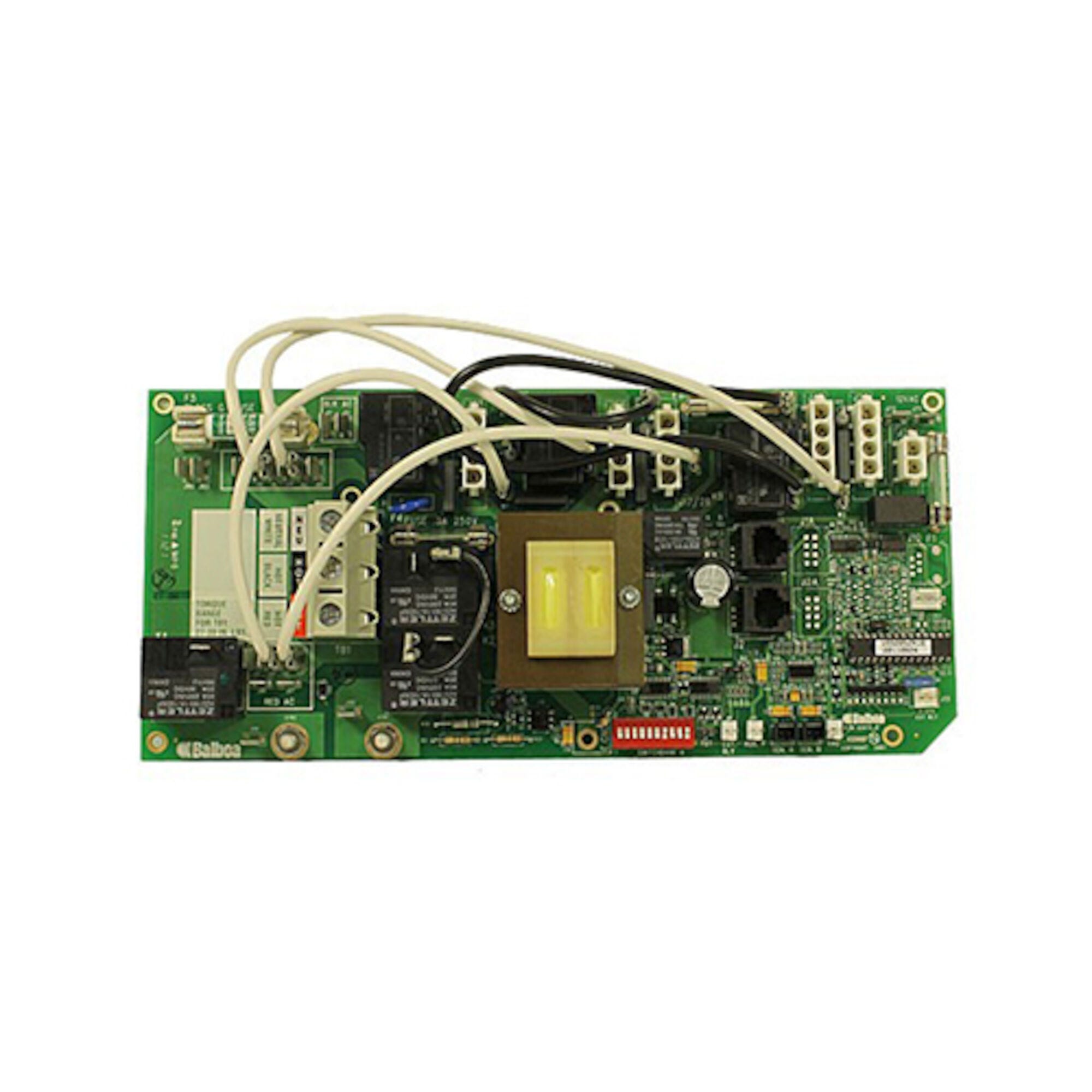
Balboa VS520SZ Spa Circuit Board — 55151-01 (VS520SZ System, Dual 2-Speed Pumps, 5.5kW, Serial Standard)
$306.33
Circuit Board, Balboa, VS520SZ, Serial Standard, 8 Pin Phone Cable, Blower or Pump 3 Option
20 in stock
Fast dispatch
Order in
--:--:--
for shipping today
💡 Balboa VS520SZ Spa Circuit Board — 55151-01 (VS520SZ System, Dual 2-Speed Pumps, 5.5kW, Serial Standard)
Professional-grade replacement main board for the Balboa VS520SZ control system — restoring full dual-pump 5.5kW spa control.
🔌 Product Overview
The Balboa VS520SZ circuit board (part number 55151 / 55151-01) is the main printed circuit board (PCB) for the Balboa VS520SZ spa control system, identified by chip number VS520SZR1A(x). The VS520SZ is the most feature-rich model in Balboa’s Value Series (VS) family, engineered around Balboa’s patented M7® temperature and water flow sensing technology — eliminating the need for a separate pressure switch and allowing the heater to be plumbed on either the suction or discharge side of the pump.
This board runs two independent 2-speed jet pumps, controls a 5.5kW electric heater, supports an optional circulation pump, a 120V/240V ozone generator, a 12V spa light, and stereo audio. A third pump output or blower can be added via the on-board J17/26 terminal with a simple DIP switch change (A7 ON). A 2-speed Pump 2 output requires the X-P332 expander board (PN 55137) mounted alongside this main board.
The 55151-01 uses a Serial Standard topside panel (PN 53189-01) connected via an 8-pin phone-style cable. It is a genuine Balboa Water Group OEM board, factory-built in the USA, and ships new and uninstalled from Parts4Tubs.
✨ Key Features
✅ Dual 2-Speed Pump Control — Drives Pump 1 and Pump 2 each at 2-speed (Pump 2 requires X-P332 expander board, sold separately); supports the most demanding multi-pump spa configurations.
✅ 5.5kW Heater Output — Full 5.5kW at 240V; the board displays a heater configuration indicator on startup so you can immediately confirm the heating mode is set correctly for your system.
✅ Balboa M7® Sensing Technology — Patented combined temperature and flow sensing eliminates the need for a separate pressure switch; heater can be plumbed on suction or discharge side of the pump.
✅ Blower or 1-Speed Pump 3 Option — J17/26 output activates with DIP switch A7 ON; adds a blower or a third 1-speed pump circuit without additional expander hardware.
✅ Optional Circulation Pump Support — Integrated circ pump output (J47) with configurable circ modes via DIP switches A5 and A9.
✅ 120V Ozone Output (Field-Configurable to 240V) — On-board ozone connector (J29) ships at a preset voltage; field-changeable via W2 wire to 120V or 240V to match your ozone generator.
✅ 12V Spa Light Output — Dedicated 12V light terminal for standard spa lighting.
✅ Stereo Audio Support — 12AV audio output for compatible spa audio systems.
✅ Serial Standard Panel via 8-Pin Phone Cable — Compatible with Serial Standard topside (PN 53189-01) and auxiliary panels VX20 (2-button) and VX40S (4-button).
✅ Persistent Memory (Non-Battery) — Filter cycles, set temperature, and heat mode are retained without a battery; reset via J43 jumper after any DIP switch change (except A1).
✅ Genuine Balboa Water Group OEM Board — Factory-built and tested; non-returnable policy ensures every board ships pristine and never installed.
📊 Technical Specifications
| Specification | Value |
|---|---|
| Part Number | 55151 / 55151-01 |
| Chip Number | VS520SZR1A(x) |
| Board Type | Main PCB — complete replacement control board |
| System PN | 56007-01 |
| System Model | VSP-VS520SZ-DCAH |
| Software Version | 43 |
| Base PCB Assembly | VS500Z PN 22972 Rev C or D |
| Input Voltage | 240V AC / 60Hz |
| Service Type | 4-wire (Hot-Black, Hot-Red, Neutral-White, Ground) |
| Circuit Breaker Rating | 50A maximum |
| GFCI Requirement | AC Class A GFCI protected circuit required |
| Heater Output | 5.5kW at 240V |
| Pump 1 Output | 2-Speed |
| Pump 2 Output | 2-Speed (requires X-P332 expander board PN 55137) |
| Pump 3 / Blower Output | 1-Speed via J17/26 (DIP switch A7 ON) |
| Circulation Pump | Optional — via J47; configurable via DIP switches A5 + A9 |
| Ozone Output | 120V (factory default) — field-configurable to 240V via W2 wire |
| Light Output | 12V spa light |
| Audio Output | 12AV stereo |
| Topside Connection | 8-pin phone-style cable — Serial Standard panel PN 53189-01 |
| Aux Panel Support | VX20 (2-button), VX40S (4-button) |
| Persistent Memory Reset | J43 jumper during power-up |
| Certifications | Please refer to manufacturer documentation or contact Parts4Tubs for details |
| Warranty | Please refer to manufacturer documentation or contact Parts4Tubs for details |
ℹ️ US VOLTAGE NOTE: The VS520SZ operates on 240V AC / 60Hz and requires a dedicated 4-wire service. This is not a 120V-capable board. Confirm your electrical supply before ordering.
🔗 Compatibility Guide
This board is the main PCB for:
| System | Notes |
|---|---|
| Balboa VS520SZ | Direct OEM main board replacement |
| System Pack PN 56007-01 | The complete VS520SZ spa pack assembly |
| System Pack PN 56007HC1 | HC-series VS520SZ variant |
Compatible Topside Panels:
| Part Number | Panel Name / Type |
|---|---|
| 53189-01 | Serial Standard (primary compatible topside) |
| VX20 | 2-Button Auxiliary Panel |
| VX40S | 4-Button Auxiliary Panel |
Optional Expander Board Required for Pump 2:
| Part Number | Description |
|---|---|
| 55137 (X-P332) | Required for 2-speed Pump 2 output — sold separately |
⚠️ The VS520SZ main board does not drive 2-speed Pump 2 without the X-P332 expander board (PN 55137) installed. If your spa runs two 2-speed pumps, confirm the expander is present and functional.
Replaces / Cross-Reference Part Numbers:
| Part Number | Source / Description |
|---|---|
| 55151-01 | Balboa — current revision designation |
| 33-55151 | HydroQuip cross-reference |
| 33-55151-K | HydroQuip kit cross-reference |
| 33-0033B | HydroQuip alternate reference |
| 59-138-1687 | Alternate distributor reference |
| G1157 | Balboa internal catalog reference |
| 9710-116 | Alternate cross-reference |
| VS520SZR | Chip number variant reference |
⚠️ Always identify your board by the chip number on the white label near the center of the PCB, not by visual appearance alone. Multiple VS-series boards look identical but are programmed differently.
🎛️ Board Functions & Controls
Pump Outputs:
| Output | Function | Speed |
|---|---|---|
| Pump 1 | Primary jet pump | 2-Speed (built-in) |
| Pump 2 | Secondary jet pump | 2-Speed (requires X-P332 expander PN 55137) |
| J17/26 | Blower or 1-Speed Pump 3 | 1-Speed (DIP switch A7 ON) |
| J47 | Circulation pump | Configurable (A5 + A9) |
Heater Control:
| Feature | Specification |
|---|---|
| Heater Output | 5.5kW at 240V AC |
| Sensing Technology | Balboa M7® (combined temperature + flow) |
| Hi-Limit Protection | Yes — built into M7 sensor system |
| Startup Display | “H” = 3–6kW heater configured (correct for 240V VS520SZ) |
Additional Outputs:
| Function | Specification |
|---|---|
| Ozone | 120V default (field-configurable to 240V via W2 wire) |
| Spa Light | 12V |
| Audio | 12AV stereo |
DIP Switch Summary:
| Switch | Function |
|---|---|
| A1 | Test Mode — normally OFF |
| A2 + A10 | High-speed pump/blower count before heater disabled (Table 1) |
| A3 | N/A — must be OFF |
| A4 | Aux Freeze — must be OFF |
| A5 + A9 | Pump 1 speed and Circ Pump mode |
| A6 | OFF = 60Hz (US); ON = 50Hz |
| A7 | ON = J17/26 enabled (Blower/Pump 3); OFF = J17/26 disabled |
| A8 | OFF = °F display; ON = °C display |
⚠️ After changing any DIP switch other than A1, you must reset Persistent Memory (J43) for the new settings to take effect.
Persistent Memory Reset Procedure:
- Power down — disconnect power from the spa
- Place a jumper across both pins of J43
- Power up — connect power to the spa
- Wait until the display shows the standby temperature
- Power down again
- Remove jumper from J43 (or move to cover one pin only)
- Power up — the new DIP switch settings are now active
⚙️ Installation Requirements
⚠️ IMPORTANT: Installation must be carried out by a licensed electrician in compliance with NEC (National Electrical Code) and local codes.
Pre-Installation Checklist:
- [ ] Confirm chip number VS520SZR1A(x) on your existing board’s white label
- [ ] Verify the board is for a VS520SZ system (system pack PN 56007-01 or variant)
- [ ] Disconnect all power at the breaker and disconnect box before beginning
- [ ] Photograph all existing wiring connections before removal
- [ ] Allow capacitors to discharge — wait at least 5 minutes after power-off
- [ ] Confirm whether your system uses the X-P332 expander board (PN 55137) for Pump 2
- [ ] Note your existing DIP switch positions before removing the old board
Electrical Requirements:
| Requirement | Specification |
|---|---|
| Supply Voltage | 240V AC / 60Hz |
| Service Type | 4-wire (hot-black, hot-red, neutral-white, ground) |
| Circuit Breaker | 50A maximum |
| GFCI Protection | AC Class A GFCI required (per NEC Article 680) |
| Ground Connection | Mandatory — equipment grounding + bonding per NEC Article 680 |
| Dedicated Circuit | Required |
| Disconnect Box | Required within line of sight of spa (per NEC) |
Key Wire Connections:
| Terminal | Function | Color |
|---|---|---|
| TB1 | Main power input (Hot/Hot/Neutral) | Black / Red / White |
| E.GND | Equipment ground | Green |
| J1 | Topside panel (8-pin phone cable) | — |
| J47 | Circulation pump | — |
| J29 | Ozone connector | — |
| J17/26 | Blower or Pump 3 (when A7 ON) | — |
| J43 | Persistent Memory reset jumper | — |
💡 Tip: Copy your existing DIP switch settings to the new board before reinstalling. After powering up, perform the Persistent Memory reset (J43) to ensure the new settings take effect. Verify the startup display shows the correct heater configuration indicator.
⚠️ Safety Warnings
Electrical Safety:
- ⚠️ ALWAYS disconnect power at the breaker and disconnect box before any work on the spa pack
- ⚠️ Installation by a licensed electrician only
- ⚠️ This board requires 240V AC / 60Hz on a 4-wire service — verify your electrical supply before connecting
- ⚠️ AC Class A GFCI protection is required by NEC Article 680 for all spa installations
- ⚠️ Never operate the spa with covers removed from electrical components
- ⚠️ All wiring must comply with NEC and applicable local electrical codes
- ⚠️ TB1 terminal block torque range: 27–30 in. lbs. — do not over-tighten
Ozone Connector Voltage Warning:
- ⚠️ Changing the ozone connector voltage (W2 wire) also changes the voltage to the circ pump connector (J47). If a circ pump is installed, verify it is rated for the selected voltage before making this change.
Water & Electrical Safety:
- ⚠️ Ensure no water ingress into the control box during or after installation
- ⚠️ Check all seals and gaskets during the installation
- ⚠️ Never handle electrical components with wet hands
DIP Switch Safety:
- ⚠️ Setting DIP switches incorrectly may cause abnormal system behavior and damage to components
- ⚠️ Turn main power OFF before adjusting any DIP switch
- ⚠️ Always reset Persistent Memory (J43) after changing any DIP switch other than A1
Post-Installation:
- ⚠️ Verify the startup display shows the correct SSID and heater configuration
- ⚠️ Test all safety features — particularly hi-limit sensor — before returning the spa to service
- ⚠️ Check for error codes on initial startup
🔍 Error Codes & Startup Diagnostics
Power-Up Display Sequence:
| Display | Meaning |
|---|---|
| Three-digit SSID number (shown three times) | System Software ID — third display is the software version (should be 43 for VS520SZ) |
| “H” indicator | System configured for 3–6kW heater — correct for 240V VS520SZ operation |
| “C” indicator | System configured for 1–3kW heater — indicates 120V mode; should NOT appear on a VS520SZ |
| Priming Mode indicator | Normal — signals the end of the power-up sequence |
Common DIP Switch Troubleshooting:
| Symptom | Likely Cause | Action |
|---|---|---|
| Breaker trips immediately | Voltage or wiring configuration error | Verify 4-wire 240V service; check all wiring against tech sheet |
| Pump 2 does not operate | X-P332 expander (PN 55137) missing or not connected | Confirm expander board is installed and RJ45 cable is fully seated |
| New DIP switch settings ignored | Persistent Memory not reset | Perform J43 reset procedure (see Board Functions section above) |
| Pump controls wrong outputs | Mode / DIP switch misconfiguration | Re-check A5 + A9 settings against Table in tech sheet; reset Persistent Memory |
| Display shows “C” instead of “H” | Board configured for low-power / 120V mode | Check A2 + A10 DIP switch settings against Table 1 in tech sheet |
| Blower / Pump 3 unresponsive | J17/26 not enabled | Set DIP switch A7 to ON; reset Persistent Memory |
⚠️ Refer to the VS520SZ tech sheet (see Downloads section) for the complete wiring diagram and DIP switch configuration table before making any adjustments.
🎯 Ideal Applications
| Application | Suitability | Notes |
|---|---|---|
| ♨️ Balboa VS520SZ systems | ✅ Direct OEM main board replacement | Exact match for system PN 56007-01 |
| ♨️ 2-pump hot tubs requiring 5.5kW heating | ✅ Full-featured replacement | Controls two 2-speed pumps + heater + optional circ + blower |
| ♨️ Spas using Serial Standard topside (PN 53189-01) | ✅ Compatible | 8-pin phone cable connection |
| ♨️ Hot tubs needing blower or third pump output | ✅ Configurable | J17/26 output enabled via DIP switch A7 |
| ♨️ Spas with optional circ pump | ✅ Configurable | J47 circ pump output with multiple circ modes |
This board is designed for:
- Replacing a failed VS520SZ main board in an existing Balboa 56007 series spa pack
- Restoring full dual-pump, 5.5kW spa functionality to VS520SZ-based hot tubs
- Technicians servicing VS-series spas requiring a genuine Balboa replacement main PCB
❓ Frequently Asked Questions
Q: How do I confirm this is the right board for my spa? A: Find the chip number on the white label near the center of your existing board. It must read VS520SZR1A(x) (where x is a revision letter). You can also check the system pack sticker for PN 56007-01. Never order by appearance alone — many VS boards look identical.
Q: Do I need the X-P332 expander board as well? A: If your spa runs a 2-speed Pump 2, yes — the main 55151-01 board does not include the Pump 2 relay circuit. You need the X-P332 expander board (PN 55137), sold separately. If Pump 2 in your system is 1-speed or controlled via J17/26, the expander may not be required — consult your spa’s wiring diagram.
Q: This is a 240V board — will it work on a 120V supply? A: No. The VS520SZ operates on 240V AC / 60Hz on a 4-wire service (50A max). It is not a convertible 120V/240V board. Verify your electrical service before ordering.
Q: What topside panels are compatible? A: The 55151-01 uses a Serial Standard topside panel (PN 53189-01) via an 8-pin phone-style cable. The VL600 or VL701 are commonly paired with this system. Auxiliary panels VX20 (2-button) and VX40S (4-button) are also supported. Contact Parts4Tubs if you are unsure about your current panel.
Q: Do I need to reconfigure DIP switches after installing the new board? A: Yes. Transfer your DIP switch settings from the old board (photograph them first), then perform a Persistent Memory reset using the J43 jumper after power-up. This is mandatory — new settings will not take effect until the reset is completed.
Q: The display showed “C” after power-up instead of “H” — is something wrong? A: The “C” indicator means the board is in 120V / low-power heater mode, which is incorrect for a VS520SZ. Check DIP switch settings A2 and A10 against Table 1 in the tech sheet and reset Persistent Memory via J43.
Q: Can I return this board if it turns out to be the wrong one? A: Circuit boards are non-returnable. Please confirm your chip number and part number before ordering. Contact Parts4Tubs — our team will help you verify the correct board for your system.
Q: What warranty does this board carry? A: Covered under the Balboa Water Group manufacturer’s warranty. Contact Parts4Tubs for full warranty terms and conditions.
📥 Downloads & Resources
📄 VS520SZ Tech Sheet — 56007-01_B — Official Balboa tech sheet including full wiring diagram, DIP switch definitions, and panel configurations
🏆 Why Choose the Balboa VS520SZ Board (55151-01)
✅ Genuine Balboa Water Group OEM Board — Manufactured by Balboa, the original designer of the VS520SZ system; not an aftermarket clone
✅ Patented M7® Technology — Combined temperature and flow sensing eliminates pressure switch failures; most reliable VS-series architecture
✅ Full 5.5kW Heating at 240V — Maximum heating power for VS-series spas; confirmed in the official tech sheet
✅ Two 2-Speed Pumps Supported — Top-tier VS configuration for dual-zone jet control (Pump 2 with X-P332 expander)
✅ Configurable Blower or Third Pump — J17/26 output adds flexibility for diverse spa plumbing configurations
✅ Persistent Memory Without a Battery — Filter cycles and temperature settings retained through power outages
✅ Factory-New, Never Installed — Non-returnable policy ensures every board shipped is pristine and direct from the factory
🛒 Why Buy From Parts4Tubs
✅ Fast US shipping on in-stock parts
✅ Expert technical advice from spa specialists who know Balboa VS-series systems inside and out
✅ Competitive pricing on genuine OEM boards
✅ Full warranty support — we help you navigate manufacturer claims
✅ Easy returns within 30 days on eligible items (circuit boards are non-returnable per manufacturer policy)
✅ Compatible expander boards, topside panels, and accessories available
✅ Help identifying the correct board using your chip number and system part number
⭐ Summary
The Balboa VS520SZ circuit board (55151 / 55151-01) is the genuine OEM main PCB for Balboa’s top-tier VS500 series control system. Running on 240V / 60Hz with a 50A circuit, it drives two independent 2-speed jet pumps (Pump 2 with optional X-P332 expander), a 5.5kW heater using Balboa’s patented M7® sensing technology, an optional circ pump, ozone generator, 12V light, and stereo audio. Configurable via DIP switches A1–A10, it pairs with a Serial Standard topside via 8-pin phone cable. Order from Parts4Tubs for fast US shipping and expert technical support — verify your chip number (VS520SZR1A(x)) before purchasing, as circuit boards are non-returnable.
Finding and identifying a replacement Hot Tub Circuit Board (PCB)
If you are looking to replace a failed PCB on your Hot Tub’s spa pack, then quite often identifying the part that you need can be the hardest thing.
Firstly, you are looking for a model number on the actual circuit board itself. Having the model or serial of your hot tub is not going to help at this point, you need to find the number on the PCB itself.
Now, with certain brands of PCB, the number of the replacement PCB that you need is not going to match identically the one you are replacing. Why is that I hear you ask?
Well, normally, it is an updated version. This means that it might have updated firmware on the PCB or be a later revision. Normally, this means that the part number would be slightly different. This is usually indicated with a “12345678 -x” at the end of that part number where x indicated a firmware revision.
In some cases, there will be some following letters on the part number of the circuit board, “12345678 -x MAS” this can indicate that the PCB was used for an OEM meaning it was produced for a certain hot tub manufacturer and the letters identify the manufacturer.
This means if you source an original PCB, it will not have the letters, but will in most cases work just fine.
It can be confusing I know!
What if you can’t find a model number?
If you can’t find a model number on the PCB itself, then you need to look for a model number on the spa pack. Normally, there is a sticker on the outside of the spa pack that tells you the current ratings and input voltages etc and this will have a model number.
In general, most spa packs in the USA are manufactured by Balboa, Hydro-Quip, ACC or Gecko. I know I am generalising here, but if you have a spa pack that has the brand of your hot tub on, it will be an OEM so the key is identifying who made the original box.
From there, you can normally find an original PCB that you will be able to switch out.
For example, the Balboa VS (value series) is a very popular spa pack that has been used by multiple hot tub manufacturers under their own brand names. Whatever they have called it, strip it back and it is still a Balboa VS.
Visual Inspection
One of the most important things you can do when you are looking for a replacement is to visually inspect the PCB that you have versus the picture online of the replacement you are considering. They need to look the same even if there are the differences in firmware revisions or OEM part numbers, you should be visually replacing a PCB that looks like the one you have.
Configuring a replacement Hot Tub Circuit Board (PCB)
When you get a new PCB, you are more than likely going to need to configure it. Most PCBs have a number of different modes and setups that the can operate in. For this, you will need to manual or spec sheet to guide you.
For things like DIP switches, most of the time you can copy the settings from your original circuit board. You are looking for things like setting the voltage as a lot of PCBs can be configured to run on both 115V and 230V.
You may need to move jumpers or even wires to configure voltages – the key here is that you read the schematic and don’t expect the PCB to just work out of the box – it usually doesn’t.
Troubleshooting a Hot Tub Circuit Board (PCB)
Here are some common things you will see when you replace a PCB on a hot tub.
You press the buttons on the topside control and they don’t control the right parts (pumps or blower etc) – this is a mode configuration thing and you will either need to change some DIP switches on the PCB or an internal or low level programming mode on the topside control. Check the manual for how to do this.
You turn on the hot tub and it trips the breaker – it is not common for a new PCB to fail out of the box (I have not seen one yet!) However, a common mistake is that the voltage has not been set correctly. If it is set for 115V and then you try and turn it on, the current draw will be a lot more (twice) than expected and the breaker will trip.
To check this, unplug all of your kit – heater, pumps, blower and then turn on the PCB. If it trips with nothing plugged in, usually the voltage is incorrectly set and what is happening is that live current is being sent to the ground – because you have 4 wires into the PCB rather than 3. Current on the ground loop causes the trip. Check the settings to make sure it is configures for 230V.
It might not trip until you physically turn on a pump or a blower. As mentioned, if the pack is set to 115V and your pump is meant for 230V, it will draw twice the current at half the voltage and trip your breaker. Check the manual for info on how to set the voltage.
| Brand | Balboa |
|---|
Related products
Gecko Spa Pack Controls
Gecko in.yt Spa Control 4.0kW Flow Thru Heater 0611-221031-361
$752.14
$481.65
Out of stock
Hydro-Quip Spa Pack Controls
Hydro-Quip M1 Spa Control 1.0/4.0kW Low Flow Heater CS9234M1-F-U-LF
$987.06
Out of stock
Gecko Heating
$94.51

Balboa Circuit Boards
Balboa RS101 Spa Circuit Board — 456404-1 (Dream Maker / AquaRest OEM)
$373.96

Sundance Circuit Boards
Sundance® / Jacuzzi® 6600-297 J-300 LED Series Spa Circuit Board (2-Pump, CLEARRAY® On-Demand)
$590.80
Gecko Spa Pack Controls
$343.01
Sundance Circuit Boards
$915.79