
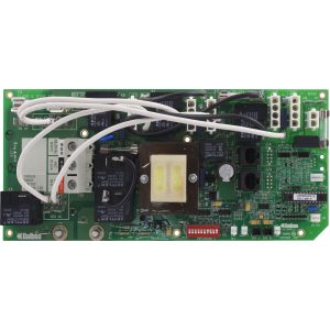
Balboa VS511 Expander Board — 53426 (X-2SP, VS511Z / VS511SZ / EL Systems, 2-Speed Pump)
$88.29
Circuit Board, Expander, Balboa, VS511/511SZ, 2-Speed Pump, Less AMP Cable
27 in stock
💡 Balboa VS511 Expander Board — 53426 (X-2SP, VS511Z / VS511SZ / EL Systems, 2-Speed Pump)
Expand your Balboa VS511 or EL series spa control system to support a second 2-speed pump — with this genuine OEM daughter board.
📋 Product Overview
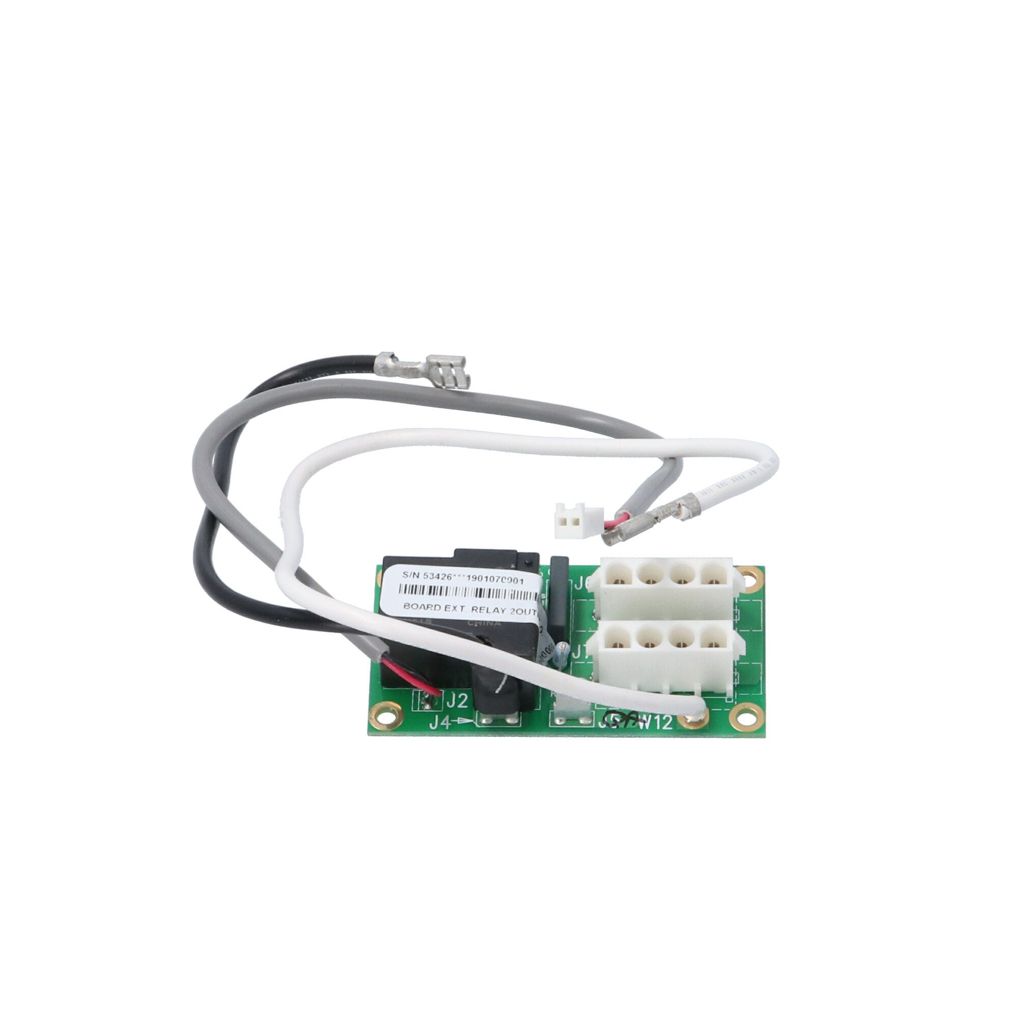
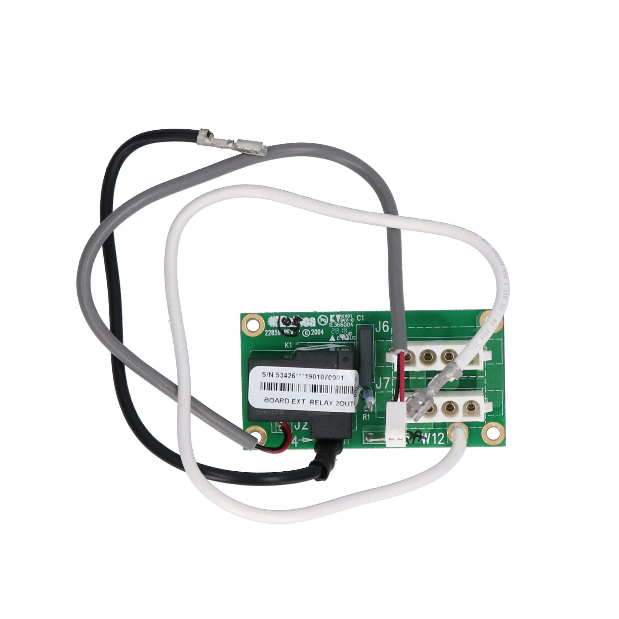
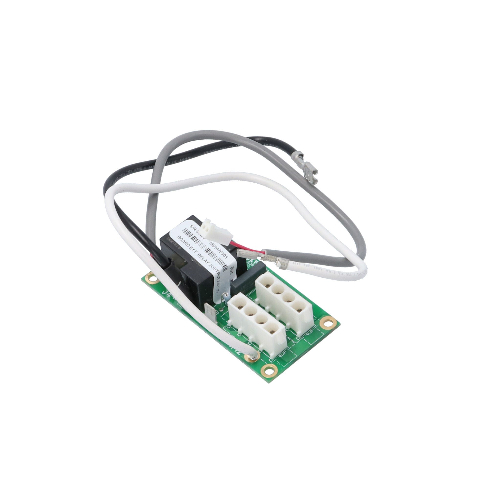
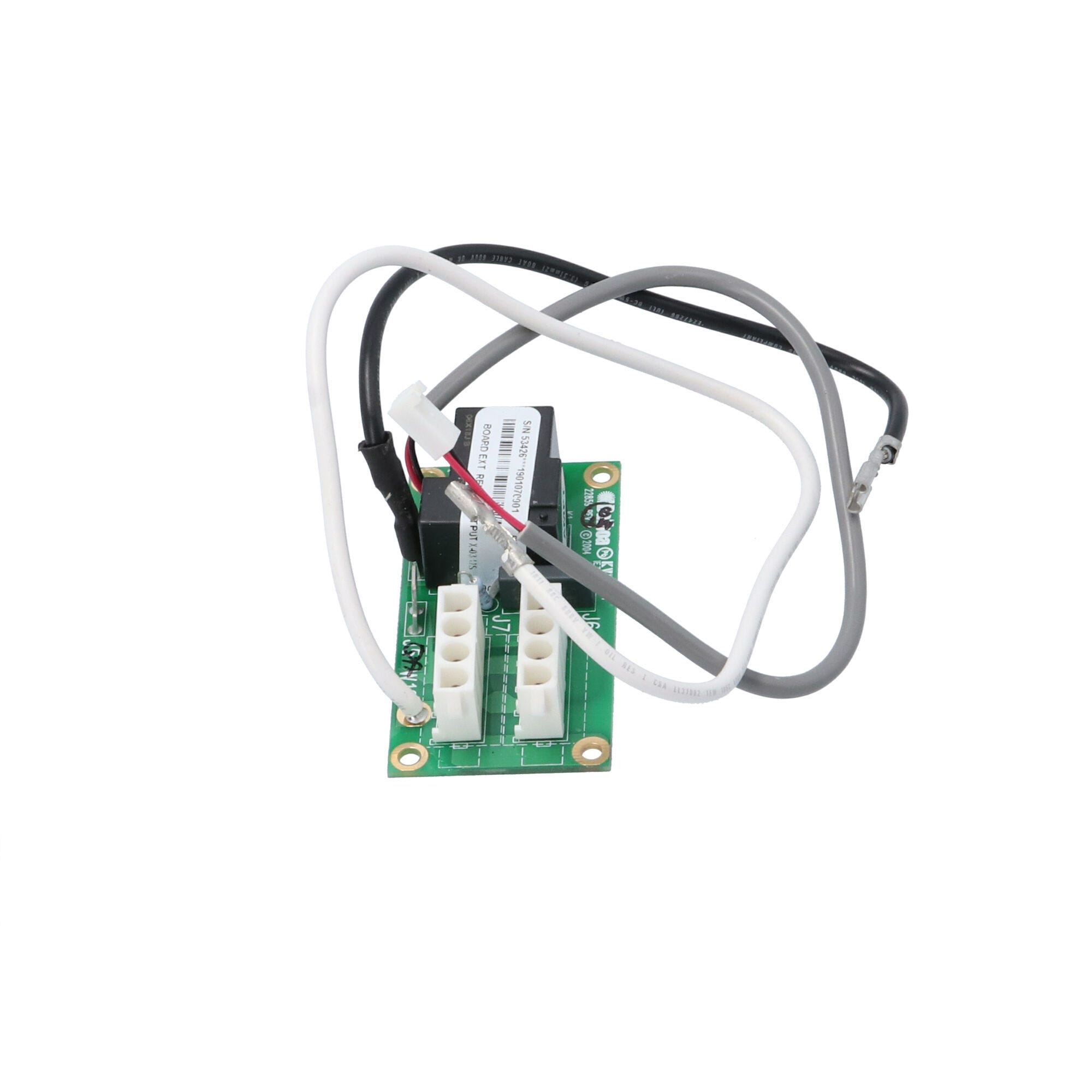
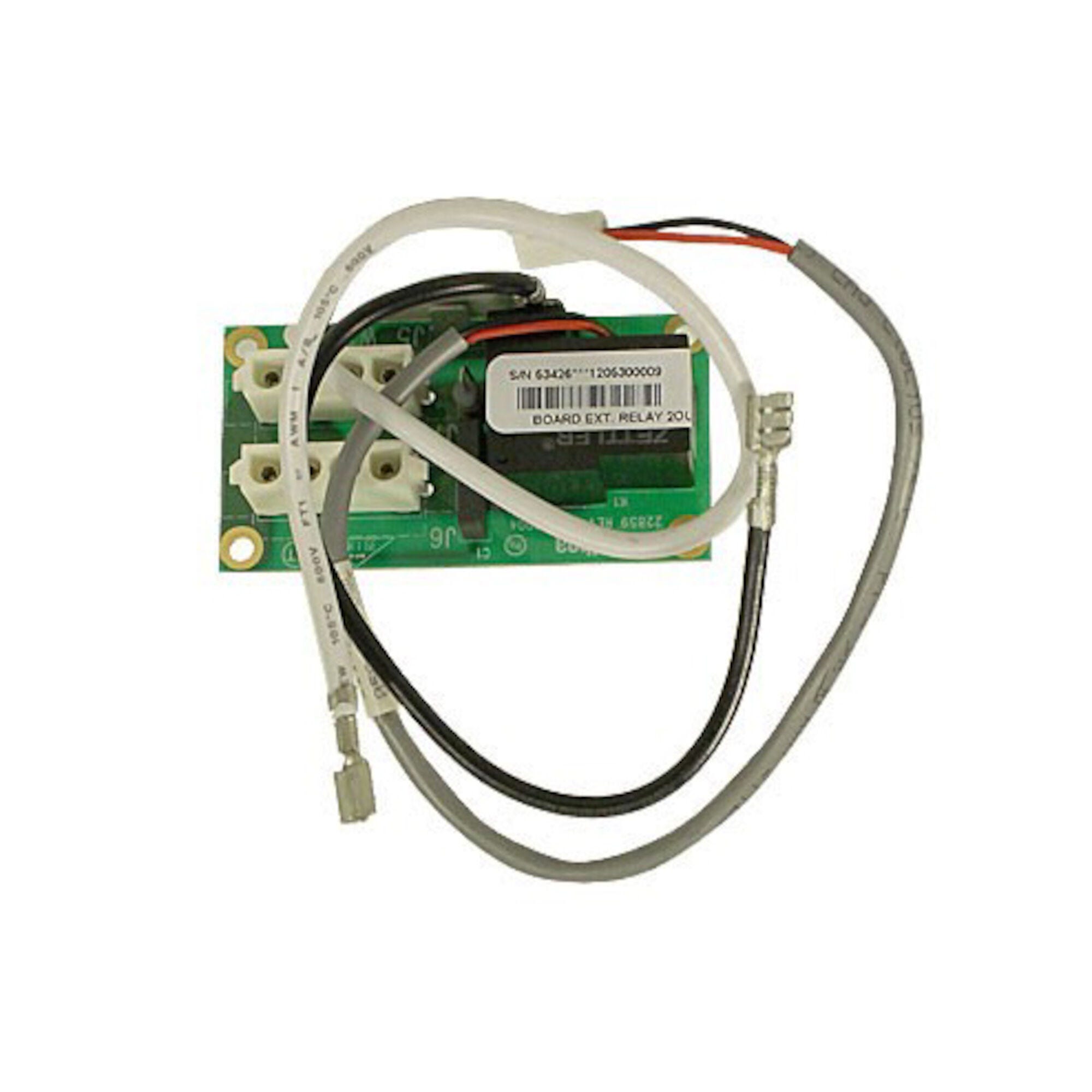
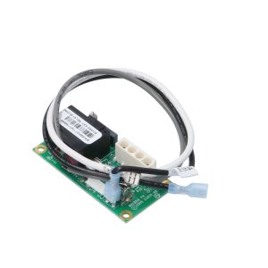
The Balboa VS511 Expander Board (Part Number 53426, model X-2SP) is a genuine OEM daughter board manufactured by Balboa Water Group® that adds a second 2-speed pump output to compatible VS511Z, VS511SZ, and EL series spa control systems. It mounts inside the spa pack enclosure and connects directly to the main VS500Z PCB via the expander relay terminals.
The VS511Z system supports two 2-speed jet pumps as part of its standard configuration — but the main board alone cannot drive a 2-speed Pump 2 without this expander board connected. Per the official Balboa VS511Z Hot Sheet, when a 2-speed Pump 2 is installed, the X-2SP expander board (53426) is required and wiring connects through dedicated expander terminals (J4–J7) on the main board.
This board ships without AMP-style connecting cables. It is the board-only version, intended for technicians reusing the original wiring. If you also need replacement cables, order the complete 53913 kit instead.
Balboa Water Group designates the G1960 as an alternate reference name for this board. It carries a 1-year manufacturer’s warranty.
✨ Key Features
- ✅ Genuine Balboa OEM Expander Board — Part number 53426, model designation X-2SP; manufactured by Balboa Water Group®; also referenced as G1960
- ✅ Adds 2nd 2-Speed Pump Output — Provides the Pump 2 relay outputs needed for a 2-speed secondary jet pump — required for VS511Z and VS511SZ dual-pump configurations
- ✅ 2 Receptacles / 1 Relay Design — Two receptacle connections and one dedicated relay; 12A maximum load
- ✅ Molex-Style Connector — Uses a Molex-style plug connection for the expander interface
- ✅ Compatible with VS511Z, VS511SZ, and EL Series — Verified in the official Balboa VS511Z Hot Sheet; also compatible with EL series main boards
- ✅ Replaces 53913 Board (Without Cables) — Can replace the 53913 expander kit when the original removable cables are being reused; use 53913 if cables are also needed
- ✅ PDF-Documented Integration — Wiring positions and connection requirements fully documented in the official Balboa VS511Z Hot Sheet (System PN 54382-01)
- ✅ 1-Year Manufacturer’s Warranty — Backed by Balboa Water Group’s 1-year limited warranty
⚙️ Technical Specifications
| Specification | Value |
|---|---|
| Manufacturer Part Number | 53426 |
| Board Model / Type Designation | X-2SP |
| Alternate Reference | G1960 |
| Board Type | Expander / Daughter Board — NOT standalone |
| Function | Adds 2nd 2-speed pump (Pump 2) output |
| Number of Receptacles | 2 |
| Number of Relays | 1 |
| Max Load | 12A |
| Connector Type | Molex-style plug |
| Cables Included | ⚠️ No — this is the board only (“Less AMP Cable”) |
| Fuse Included | No onboard fuse on this model |
| System Voltage | Matches host system (240VAC / 60Hz for VS511Z) |
| Board Dimensions | Approx. 3.125 in × 1.625 in (79mm × 41mm) |
| Warranty | 1 year (Balboa Water Group manufacturer’s warranty) |
⚠️ No cables are included with this board. If you need cables, order the 53913 expander kit instead.
ℹ️ US VOLTAGE NOTE: The VS511Z system operates on 240VAC / 60Hz. This expander board operates at the voltage of its host system. Always verify your main board configuration before installing.
🔗 Compatibility Guide
Compatible Main Control Systems
| System | Description |
|---|---|
| VS511Z | Balboa Value Series VS511Z — primary compatible system |
| VS511SZ | Balboa Value Series VS511SZ |
| EL Series | Balboa EL series spa control systems |
Associated Part Numbers
| Number | Type |
|---|---|
| G1960 | Alternate Balboa reference name for this board |
| X-2SP | Board model/type designation |
| 53913 | Full expander kit WITH cables — use when cables also needed |
| 33-53426-K | Kit variant reference |
| 389283 | Alternate reference |
| X-03 | Alternate model reference |
| 3-60-0099 | Alternate catalog reference (Parts4Tubs alternate number) |
Also Compatible With These OEM System Part Numbers
Per pool-n-spa.com: used in systems 53755, 53787, 53889, 54384, 54384-01 (Leisure Bay, Coast Spas, Viking Spas, and other OEM variants using VS511-series boards).
⚠️ Always verify your main board is compatible before ordering. Do not order based on physical appearance alone — many Balboa expander boards look similar but serve different systems.
🎛️ How This Expander Board Works
The 53426 connects to the main VS500Z PCB via dedicated expander relay terminals inside the control box. Once connected, it provides the high-speed and low-speed relay outputs that drive Pump 2.
Connection Points (from Official Balboa VS511Z Hot Sheet, PDF p.4)
| Expander Terminal | Connected To | Function |
|---|---|---|
| J4 | Main board expander terminal | Relay signal routing |
| J5 | Main board expander terminal | Relay signal routing |
| J6 | Main board expander terminal | Pump 2 output wiring |
| J7 | Main board expander terminal | Pump 2 output wiring |
| W12 | Main board W12 wire | Power connection |
Relay Output
| Output | Function | Max Load |
|---|---|---|
| Pump 2 (2-Speed) | High speed and low speed operation | 12A |
Important Installation Notes from the Official Balboa VS511Z Hot Sheet
- ℹ️ PCBA Rev D main boards only: A black jumper on the main board is required and must not be removed. This is documented on the wiring diagram page of the VS511Z Hot Sheet.
- ℹ️ DIP switch A9: Must be set to ON if a circ pump is also installed on the VS511Z system. When A9 is OFF (no circ pump), DIP switch A5 is disabled.
- ℹ️ Ozone and Circ Pump voltage: Must be the same voltage (both 120V or both 240V). Changing ozone connector voltage also changes the circ pump connector voltage.
- ℹ️ Persistent Memory reset: After any DIP switch change (except A1), J43 must be reset or the new settings will not take effect.
🔧 Installation Requirements
⚠️ IMPORTANT: Installation must be carried out by a licensed electrician in compliance with NEC (National Electrical Code) Article 680 and all applicable local codes.
Pre-Installation Checklist
- [ ] Confirm your main board is a compatible VS511Z, VS511SZ, or EL series system
- [ ] Confirm you do NOT need new cables — if cables are also needed, order 53913 instead
- [ ] Disconnect all power at the breaker and disconnect box before starting
- [ ] Photograph all existing wiring and expander connections before work begins
- [ ] Allow capacitors to discharge — wait at least 5 minutes after power-off
- [ ] Confirm that the black jumper is present on VS511Z PCBA Rev D main boards at J1
Electrical Requirements
| Requirement | Specification |
|---|---|
| Supply Voltage | 240VAC / 60Hz (VS511Z system) |
| Max Pump 2 Load | 12A |
| GFCI Protection | Required — Class A GFCI per NEC Article 680 (provided by main system) |
| Ground Connection | Equipment grounding and bonding per NEC Article 680 (through main system) |
| Disconnect Box | Required within line of sight of spa; at least 5 feet from spa walls per NEC |
💡 Tip: Follow the wiring diagram on the back of your spa pack cover. Copy all DIP switch settings from your existing board. If any DIP switches are changed during installation, reset Persistent Memory (J43 jumper procedure) before powering up.
⚠️ Safety Warnings
- ⚠️ This is NOT a standalone board — it only operates when correctly connected to a compatible VS511Z, VS511SZ, or EL series main control board
- ⚠️ No cables are included — this is the board only; do not attempt installation without proper connection cables (use 53913 if cables needed)
- ⚠️ ALWAYS disconnect all power at the breaker and disconnect box before any work
- ⚠️ Installation by a licensed electrician only — required by NEC Article 680 and most local codes
- ⚠️ Do not exceed 12A load — overloading the relay output will cause failure or fire risk
- ⚠️ On PCBA Rev D main boards: do not remove the black jumper — it is required for correct expander board operation
- ⚠️ Persistent Memory (J43) must be reset after any DIP switch change (except A1) or the system may malfunction
- ⚠️ Ozone and circ pump connectors share voltage settings — changing one changes the other; verify both are correct before powering up
🎯 Ideal Applications
| Application | Suitability | Notes |
|---|---|---|
| ♨️ VS511Z — enabling 2nd 2-speed pump | ✅ Required component | Documented in VS511Z Hot Sheet as the required expander for Pump 2 |
| ♨️ VS511SZ — enabling 2nd 2-speed pump | ✅ Compatible | Confirmed in multiple authorized distributor sources |
| ♨️ EL series spa — enabling 2nd 2-speed pump | ✅ Compatible | Confirmed by SpaDepot and SpaGuts |
| ♨️ Replacing a failed 53426 expander board | ✅ Direct replacement | Reuse existing cables; otherwise order 53913 |
| ♨️ Replacing a failed 53913 expander kit | ✅ Compatible (board only) | Use 53426 only if original cables are being reused |
❓ Frequently Asked Questions
Q: Can this board work on its own to control my spa? A: No. The 53426 is a daughter board — it mounts inside the control box alongside a compatible Balboa main board to add a second 2-speed pump output. It cannot function independently.
Q: My system is a VS511Z and my Pump 2 has stopped working — do I need this board? A: If your spa has a 2-speed Pump 2 and the VS511Z is not running it, this expander board is likely the component to check. Confirm the 53426 is correctly seated and connected to the main board, and check for any visible damage. If replacing a failed expander, this is the correct part.
Q: What’s the difference between the 53426 and the 53913? A: Both boards provide the same 2-speed Pump 2 expander function. The 53913 is the complete kit that includes the board plus all connecting cables. The 53426 is the board only — use it when the original removable cables are being reused and no new cables are needed.
Q: Is this board compatible with EL series systems? A: Yes. The 53426 is compatible with both VS511/VS511SZ and EL series main control boards. Confirm your main board part number before ordering.
Q: What is the G1960? A: G1960 is an alternate reference name Balboa uses for the 53426 expander board. They are the same component.
Q: Do I need a licensed electrician to install this? A: Yes. NEC Article 680 and most local codes require a licensed electrician for all hot tub electrical work. This board is installed inside the live high-voltage control box of the spa.
Q: What warranty is included? A: Balboa Water Group’s standard 1-year manufacturer’s limited warranty. Circuit boards are non-returnable after installation except for verified warranty defects.
🏆 Why Choose the Balboa VS511 Expander Board 53426
- ✅ Genuine Balboa OEM Board — Manufactured by Balboa Water Group to original production standards
- ✅ PDF-Documented Wiring — Connection positions and installation requirements fully documented in the official Balboa VS511Z Hot Sheet
- ✅ Compatible with VS511Z, VS511SZ, and EL Series — Covers the full range of applicable Balboa systems
- ✅ Board-Only Value — If your cables are intact, this board-only version avoids paying for cables you don’t need
- ✅ 1-Year Manufacturer’s Warranty — Backed by Balboa Water Group
🤝 Why Buy from Parts4Tubs
- ✅ US-based company with knowledgeable local support
- ✅ Fast US shipping
- ✅ Expert technical advice from spa specialists who know Balboa VS and EL systems
- ✅ Competitive pricing on genuine OEM parts
- ✅ Full manufacturer warranty support
- ✅ Also stock the 53913 kit if you need the version with cables
- ✅ Help identifying the correct expander board for your system — contact us with your main board model number
✨ Summary
The Balboa VS511 Expander Board (53426, model X-2SP) is a genuine OEM daughter board that adds a 2nd 2-speed pump output to compatible VS511Z, VS511SZ, and EL series spa control systems. With 2 receptacles, 1 relay, and a 12A maximum load, it provides the Pump 2 outputs required for dual-pump VS511 systems. This version ships without connecting cables — use it when your original cables are being reused, or order the 53913 kit if cables are also needed. As documented in the official Balboa VS511Z Hot Sheet, the board connects via J4–J7 and W12 on the main PCB. It is not a standalone board and requires a compatible main control board already in place.
Finding and identifying a replacement Hot Tub Circuit Board (PCB)
If you are looking to replace a failed PCB on your Hot Tub’s spa pack, then quite often identifying the part that you need can be the hardest thing.
Firstly, you are looking for a model number on the actual circuit board itself. Having the model or serial of your hot tub is not going to help at this point, you need to find the number on the PCB itself.
Now, with certain brands of PCB, the number of the replacement PCB that you need is not going to match identically the one you are replacing. Why is that I hear you ask?
Well, normally, it is an updated version. This means that it might have updated firmware on the PCB or be a later revision. Normally, this means that the part number would be slightly different. This is usually indicated with a “12345678 -x” at the end of that part number where x indicated a firmware revision.
In some cases, there will be some following letters on the part number of the circuit board, “12345678 -x MAS” this can indicate that the PCB was used for an OEM meaning it was produced for a certain hot tub manufacturer and the letters identify the manufacturer.
This means if you source an original PCB, it will not have the letters, but will in most cases work just fine.
It can be confusing I know!
What if you can’t find a model number?
If you can’t find a model number on the PCB itself, then you need to look for a model number on the spa pack. Normally, there is a sticker on the outside of the spa pack that tells you the current ratings and input voltages etc and this will have a model number.
In general, most spa packs in the USA are manufactured by Balboa, Hydro-Quip, ACC or Gecko. I know I am generalising here, but if you have a spa pack that has the brand of your hot tub on, it will be an OEM so the key is identifying who made the original box.
From there, you can normally find an original PCB that you will be able to switch out.
For example, the Balboa VS (value series) is a very popular spa pack that has been used by multiple hot tub manufacturers under their own brand names. Whatever they have called it, strip it back and it is still a Balboa VS.
Visual Inspection
One of the most important things you can do when you are looking for a replacement is to visually inspect the PCB that you have versus the picture online of the replacement you are considering. They need to look the same even if there are the differences in firmware revisions or OEM part numbers, you should be visually replacing a PCB that looks like the one you have.
Configuring a replacement Hot Tub Circuit Board (PCB)
When you get a new PCB, you are more than likely going to need to configure it. Most PCBs have a number of different modes and setups that the can operate in. For this, you will need to manual or spec sheet to guide you.
For things like DIP switches, most of the time you can copy the settings from your original circuit board. You are looking for things like setting the voltage as a lot of PCBs can be configured to run on both 115V and 230V.
You may need to move jumpers or even wires to configure voltages – the key here is that you read the schematic and don’t expect the PCB to just work out of the box – it usually doesn’t.
Troubleshooting a Hot Tub Circuit Board (PCB)
Here are some common things you will see when you replace a PCB on a hot tub.
You press the buttons on the topside control and they don’t control the right parts (pumps or blower etc) – this is a mode configuration thing and you will either need to change some DIP switches on the PCB or an internal or low level programming mode on the topside control. Check the manual for how to do this.
You turn on the hot tub and it trips the breaker – it is not common for a new PCB to fail out of the box (I have not seen one yet!) However, a common mistake is that the voltage has not been set correctly. If it is set for 115V and then you try and turn it on, the current draw will be a lot more (twice) than expected and the breaker will trip.
To check this, unplug all of your kit – heater, pumps, blower and then turn on the PCB. If it trips with nothing plugged in, usually the voltage is incorrectly set and what is happening is that live current is being sent to the ground – because you have 4 wires into the PCB rather than 3. Current on the ground loop causes the trip. Check the settings to make sure it is configures for 230V.
It might not trip until you physically turn on a pump or a blower. As mentioned, if the pack is set to 115V and your pump is meant for 230V, it will draw twice the current at half the voltage and trip your breaker. Check the manual for info on how to set the voltage.
| Brand | Balboa |
|---|
Related products
Balboa Circuit Boards
Balboa D1SR Spa Circuit Board — 51485 (Dimension One Serial Deluxe)
$267.69

Balboa Circuit Boards
Balboa X-B Blower Expander Board Kit — 53310 (VS / EL2001 Systems)
$41.81
Out of stock
Balboa Circuit Boards
$381.94
Out of stock
Balboa Circuit Boards
$281.49
Out of stock
Balboa Circuit Boards
$290.40
Out of stock
Balboa Circuit Boards
Balboa M2/M3 Spa Circuit Board — 54122 (Millennium Series, Deluxe/Serial Standard)
$312.71

Balboa Circuit Boards
Balboa RS101 Spa Circuit Board — 456404-1 (Dream Maker / AquaRest OEM)
$321.04