


Balboa X-P632 Expander Board Kit — 53680 (EL2000 / EL2001 / EL8000 Systems)
$88.25
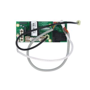
Circuit Board Kit, Expander, Balboa, X-P632, 2-Speed Pump 3, EL2001, w/2 Relays, w/Cables
22 in stock
🔩 Balboa X-P632 Expander Board Kit — 53680 (EL2000 / EL2001 / EL8000 Systems)
The genuine Balboa X-P632 two-relay expander kit for adding a 2-speed Pump 3 or dual 1-speed pump outputs to EL-series spa control systems — includes 30A fuse and cables
🔌 Product Overview
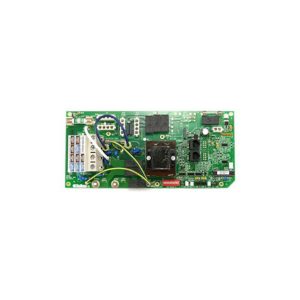
The Balboa X-P632 Expander Board (53680) is the genuine Balboa Water Group two-relay daughter board kit for adding high-power pump outputs to EL2000, EL2001, and EL8000 Mach 3 spa control systems. Designated “X-P632” (Extension-Pump 632) in Balboa’s official documentation, this expander provides two independent relay circuits that allow a 2-speed Pump 3 to run alongside the system’s primary pumps — a configuration impossible from the EL main board alone.
Unlike the single-relay X-B blower expander (53310) and single-relay X-P pump expander (53544), the X-P632 uniquely provides two relays in one board, making it the only Balboa EL-series expander capable of supporting a full 2-speed pump output from a third pump position. It can also be configured to serve two separate 1-speed pump outputs or other optional equipment setups as required by the specific spa installation.
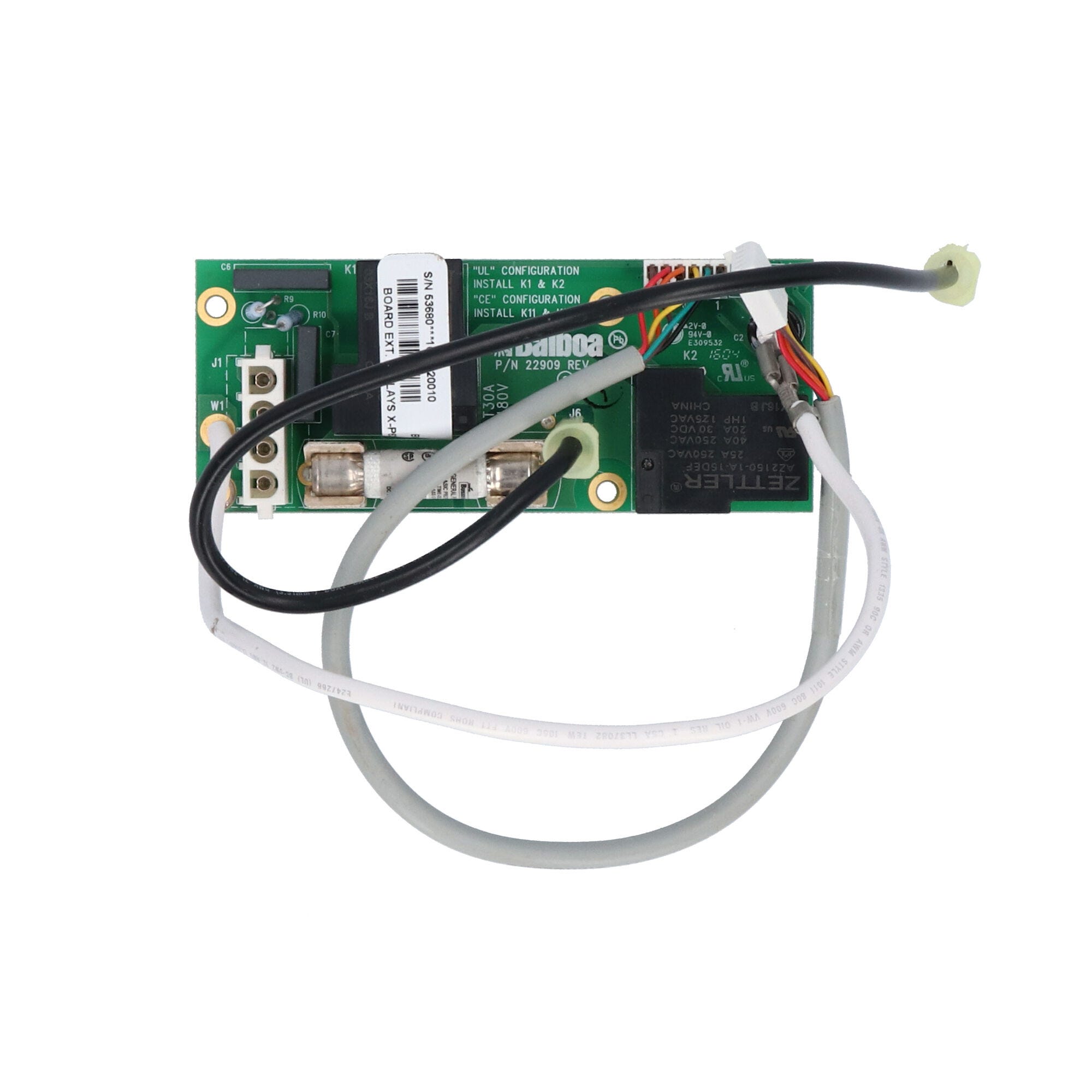
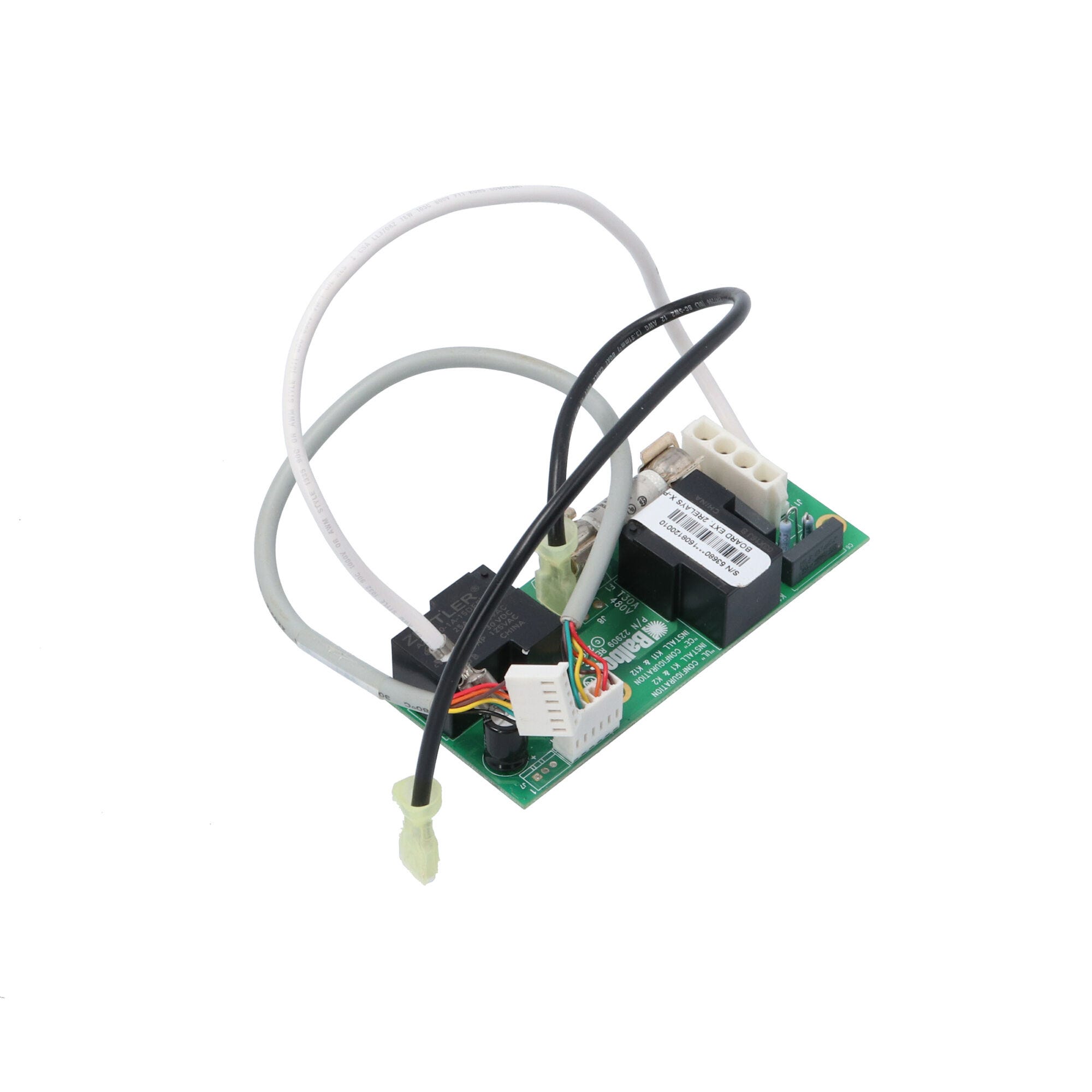
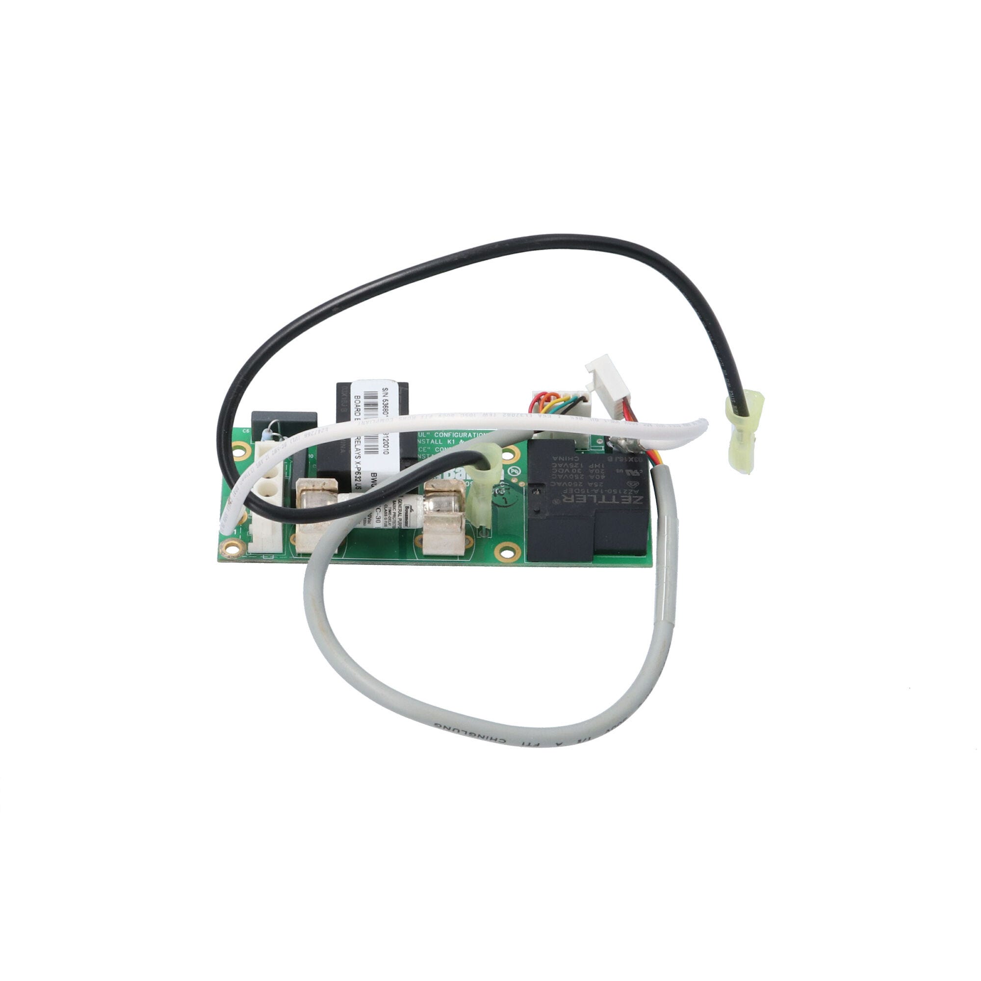
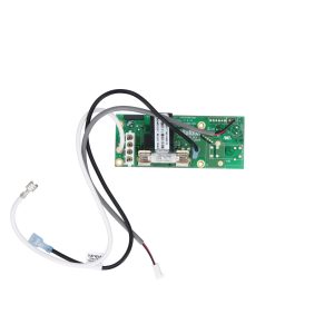
This is not a main control PCB — it is a daughter/expander board that connects to the EL main board’s dedicated “EXT. 2SP PUMP 3” expansion header (J2 and J6). The 53680 kit includes the expander PCB (PCB PN 22909 Rev B), a 30A 480V fuse, and all necessary interconnect cables.
This board is required in your spa if:
- Your EL2000, EL2001, or EL8000 system needs to operate a 2-speed third pump (Pump 3)
- You need two separate 1-speed pump outputs beyond the main board’s native capacity
- The original X-P632 board on your system has failed or is missing
- You are adding a 2-speed Pump 3 to an existing EL-series spa control system
💫 Key Features
✅ Genuine Balboa X-P632 Expander — PCB model number X-P632, PCB PN 22909 Rev B; identified as “X-P632 PN 53680” directly on the Balboa EL2001 Hot Sheet wiring diagram and configuration guide
✅ Two-Relay Architecture — The X-P632 is the only standard EL-series expander with 2 independent relays, enabling full 2-speed pump control from a single daughter board; the X-B (53310) and X-P (53544) each carry only 1 relay
✅ 30A 480V Fuse Protection — On-board 30A 480V fuse provides dedicated overcurrent protection appropriate for 2-speed pump loads; significantly higher rated than the X-B’s 10A fuse, reflecting the higher current demands of a full pump circuit
✅ Complete Kit — Board + Fuse + Cables Included — Everything needed for installation: X-P632 expander PCB, 30A 480V fuse, and all interconnect cables
✅ Multiple Output Configurations — Primary use is a 2-speed Pump 3 output; can also be wired for two separate 1-speed pump outputs or other optional setups as documented in the EL2001 Configuration Guide
✅ Compatible with EL2000, EL2001, and EL8000 — Works across the EL-series platform family; confirmed for EL2001 Mach 3 (base PCBA 53974-05) in the official Balboa tech sheet and EL2000 configuration guide; also confirmed for EL8000 Mach 3
✅ Direct Black AC Connection — J6 on the X-P632 connects directly to Black AC (1-C) on the main EL main PCBA — providing line voltage direct to the expander’s relay section for high-current pump loads
✅ DIP Switch Activated — Pump 3 is enabled via DIP switch B5 ON on the EL2001 main board; Persistent Memory (A12) must be reset for the change to take effect
✅ 1-Year Manufacturer’s Warranty — Covered under a one-year limited manufacturer’s warranty through Balboa Water Group
⚙️ Technical Specifications
| Specification | Value |
|---|---|
| Part Number | 53680 |
| Board Designation | X-P632 (Extension-Pump 632) |
| PCB Part Number | P/N 22909 Rev B |
| Board Type | Expander / Daughter Board — NOT a main control PCB |
| Number of Relays | 2 (enables 2-speed pump or two 1-speed pumps) |
| Primary Function | Adds 2-speed Pump 3 relay output to EL2000 / EL2001 / EL8000 systems |
| Secondary Functions | Two 1-speed pump outputs; other optional setups |
| On-Board Fuse | F30A 480V (30A 480V — included in kit) |
| Connector Type | Molex-style; J2 and J6 to main PCBA |
| J6 Connection | Connects directly to Black AC (1-C) on main EL PCBA |
| Kit Contents | X-P632 expander PCB + 30A 480V fuse + interconnect cables |
| Compatible Main Boards | EL2001 Mach 3 (53974-05), EL2001 Mach 2/2.1 (53414); EL2000 Mach 3 (53834-05); EL8000 Mach 3 |
| DIP Switch Activation | B5 ON on main EL board = Pump 3 enabled via X-P632 |
| Persistent Memory Reset | Required after B5 DIP change (A12 ON during power-up on main board) |
| Warranty | 1-year limited manufacturer’s warranty |
| Mounting | Compatible with X-Mount P (PN 53933) for plastic enclosure mounting |
| Physical Dimensions | Please refer to manufacturer documentation or contact Parts4Tubs |
| Certifications | Please refer to manufacturer documentation or contact Parts4Tubs |
⚠️ This is an expander/daughter board, not a standalone control board. It cannot operate independently — it must be used with a compatible Balboa EL2000, EL2001, or EL8000 main board.
🔄 Compatibility Guide
Compatible Main Control Systems
| System | Main Board PN | Notes |
|---|---|---|
| Balboa EL2001 Mach 3 | 53974-05 (base PCBA) | PDF-confirmed: X-P632 PN 53680 on Mach 3 hot sheet configuration options page |
| Balboa EL2001 Mach 2 / Mach 2.1 | 53414 and earlier | WEB-VERIFIED multiple retailers |
| Balboa EL2000 Mach 3 | 53834-05 | PDF-confirmed: EL2000 Configuration Guide explicitly shows X-P632 PN 53680 |
| Balboa EL8000 Mach 3 | See EL8000 tech sheet | WEB-VERIFIED: SpaGuts lists as “EL8000 Mach 3 Controllers” |
⚠️ Confirm your main board has the EXT. 2SP PUMP 3 expansion header before ordering. Contact Parts4Tubs with your main board part number to confirm X-P632 compatibility.
X-P632 Output Configurations
| Configuration | How | Notes |
|---|---|---|
| 2-speed Pump 3 | J2 + J6 to main EL board | Primary intended use — both relays used for one 2-speed pump |
| Two 1-speed Pumps | J2 + J6 separately wired | Each relay drives one 1-speed pump output |
| Other optional setups | Consult EL configuration guide | Check EL2000/EL2001 configuration guide for non-standard uses |
How the X-P632 Differs from Other EL Expanders
| PN | Board Name | Relays | Fuse | Primary Use |
|---|---|---|---|---|
| 53680 (this board) | X-P632 | 2 | 30A 480V | 2-speed Pump 3 or two 1-speed pumps |
| 53310 | X-B | 1 | 10A 250V | Blower (1-speed) |
| 53544 | X-P | 1 | See spec | 1-speed Pump 3 |
| 53681 / G1910 | X-P231 | 1 | 30A | High-amp 1-speed pump (direct Black AC connection) |
| 53426 / G1960 | X-O3 | — | — | Fiber-optic / color wheel setup |
ℹ️ X-P vs X-P632: The X-P (53544) provides only a single 1-speed pump output. The X-P632 (53680) provides two relay circuits, enabling a full 2-speed pump output. Do not substitute one for the other when the spa requires a 2-speed third pump.
🎛️ Board Functions & DIP Switch Configuration
What the X-P632 Provides
The X-P632 installs on the EL main PCBA at the “EXT. 2SP PUMP 3” header, adding two relay outputs. In the standard EL2001 Mach 3 configuration with this expander installed and B5 enabled, the full system output table becomes:
| Output | Specification |
|---|---|
| Pump 1 | 240V, 2-speed (main board) |
| Pump 2 | 240V, 2-speed (main board J5) |
| Pump 3 (via X-P632) | 240V, 2-speed |
| Blower | 240V (via X-B 53310 if installed) |
| Circ Pump | 120V optional |
| Ozone | 120V or 240V |
| Spa Light | 12V or 120V (per J37) |
| Heater | 5.5 kW (Mach 3 v32) or 3.0 kW (Mach 3 v28) |
DIP Switch Settings for Pump 3 via X-P632
| Switch | Setting | Function |
|---|---|---|
| B5 | ON | Pump 3 enabled — activates X-P632 relay outputs for Pump 3 |
| B6 | ON (if needed) | Alternate panel layout — ML900 scrunching enabled; Jets 3 replaces Blower on Aux panel |
| A12 | ON during power-up only | Reset Persistent Memory to apply new B5 DIP setting |
⚠️ CRITICAL: After setting DIP B5 to ON, Persistent Memory (A12) MUST be reset for Pump 3 to function correctly via the X-P632.
Persistent Memory Reset Procedure (EL2001 / EL2000)
- Power down the spa completely
- Set A12 to the ON position on the main board
- Power up and wait for the display to show the ready indication
- Set A12 back to OFF (can be done with power on using a non-conductive tool such as a pencil)
- Power up again if you powered down in the previous step
🛠️ Installation Requirements
⚠️ IMPORTANT: All electrical work on spa control systems must be performed by a licensed electrician in compliance with the National Electrical Code (NEC) Article 680 and all applicable local codes.
Pre-Installation Checklist
- [ ] Confirm your main board is a Balboa EL2000, EL2001, or EL8000 with the EXT. 2SP PUMP 3 header
- [ ] Confirm you need a 2-speed pump output — if only a 1-speed pump is required, the X-P (53544) may be more appropriate
- [ ] Disconnect ALL power at circuit breaker and GFCI before opening the control box
- [ ] Locate the J2 and J6 expansion headers on your main EL PCBA
- [ ] Verify the 30A 480V fuse is installed on the X-P632 (included in kit)
- [ ] Review the EL2001 or EL2000 Configuration Guide for your specific setup before installing
Electrical Requirements (EL2001 Main System)
| Requirement | Specification |
|---|---|
| Main System Input | 240VAC, 60Hz |
| Service Circuit Breaker | 60A maximum (Class A GFCI protected) |
| Main Board Fuse | CLASS G FUSE 30A (on main board, separate from expander fuse) |
| X-P632 On-Board Fuse | 30A 480V (provided in kit) |
| GFCI Protection | Class A GFCI required — NEC Article 680 |
| Ground Connection | Equipment grounding and bonding — NEC Article 680 |
| Dedicated Circuit | Required |
💡 Optional mounting: The X-Mount P (PN 53933) plastic enclosure mount allows the X-P632 to be mounted to the heater mounting bracket, providing a clean installed position away from the main board.
⚠️ Safety Warnings
- ⚠️ ALWAYS disconnect ALL power at the circuit breaker and GFCI before any work inside the control box
- ⚠️ Installation MUST be performed by a licensed electrician only
- ⚠️ This is an expander daughter board — it does not operate as a standalone device; it requires a compatible EL-series main board
- ⚠️ After installing and enabling via DIP B5, Persistent Memory (A12) MUST be reset — failure to do so causes the system to run with the old DIP settings
- ⚠️ The 30A fuse on this board is rated for pump loads — do not substitute a lower-rated fuse; always replace with the correct 30A 480V specification
- ⚠️ J6 on the X-P632 connects directly to Black AC (main line voltage) — no isolation; ensure all power is off before making or breaking this connection
🔍 Troubleshooting
| Symptom After Installation | Check First |
|---|---|
| Pump 3 not running after B5 set to ON | Persistent Memory (A12) not reset — repeat the reset procedure |
| 30A fuse blown on X-P632 | Pump motor drawing excessive current; verify pump motor ratings and wiring |
| Configuration error on power-up display | DIP B5 and B6 conflict or incompatible combination — review DIP definitions |
| 2-speed Pump 3 runs only 1-speed | Wiring to J2/J6 incomplete for 2-speed; verify interconnect cables |
| Panel shows Jets 3 option when blower expected | B6 may be ON — “Jets 3 replaces Blower on Aux panel” when B6 is enabled |
❓ Frequently Asked Questions
Q: Is the 53680 a replacement for my main EL2001 circuit board? A: No. The 53680 is an expander/daughter board that adds a 2-speed pump output to your existing EL main board. If your main board has failed, you need a replacement main PCB (53974-05 for EL2001 Mach 3) in addition to, or instead of, this board.
Q: What’s the difference between the X-P632 (53680) and the X-P (53544)? A: The X-P632 has two relays and a 30A fuse, enabling a full 2-speed pump output. The X-P has one relay and is designed only for 1-speed pump output. Use the X-P632 when your spa requires a 2-speed third pump.
Q: Can the X-P632 be used for a blower instead of a pump? A: The X-B (53310) is the designated blower expander for EL2001 systems. However, the EL2000 Configuration Guide notes the X-P632 “can also be used for other optional setups” — consult the Balboa EL2000 or EL2001 Configuration Guide for your specific system. For standard installations, use the X-B for blowers and the X-P632 for 2-speed pumps.
Q: Will this work with my EL8000 system? A: Yes, the X-P632 (53680) has been confirmed for use with EL8000 Mach 3 controllers. Verify that your specific EL8000 main board has the correct expansion header by referencing your EL8000 tech sheet.
Q: What DIP switch do I set for Pump 3? A: Set DIP switch B5 to ON on the main EL board to enable Pump 3. After this change, reset Persistent Memory by setting A12 ON during the next power-up, then OFF. See Installation section for the full procedure.
Q: Is there a mounting bracket for this expander? A: Yes — the optional X-Mount P (Balboa PN 53933) is a plastic enclosure mount with standoffs that attach to the heater mounting bracket, providing a secure installed position for the X-P632 inside the control box.
Q: Do I need a licensed electrician to install this? A: Yes. Any work inside a hot tub electrical enclosure falls under NEC Article 680 requirements and must be performed by a licensed electrician in most US jurisdictions.
🏆 Why Choose the Genuine Balboa X-P632 Expander (53680)?
✅ Factory OEM Two-Relay Board — Designated X-P632 PN 53680 directly on official Balboa EL2001 and EL2000 documentation; the only EL-series expander with 2 relays for full 2-speed pump control
✅ 30A 480V Fuse Rated for Pump Loads — Correctly specified for the higher amperage demands of a 2-speed pump circuit; appropriate safety margin for spa pump applications
✅ Complete Kit — Board + 30A 480V fuse + cables; nothing additional needed for a standard Pump 3 installation
✅ Cross-Platform Compatibility — Confirmed for EL2000, EL2001 (Mach 2 & 3), and EL8000 Mach 3 main boards
✅ Enables Full Three-Pump Configuration — The 53680 is what makes simultaneous 2-speed P1, 2-speed P2, and 2-speed P3 operation possible on an EL-series system
✅ 1-Year Manufacturer’s Warranty — Backed by Balboa Water Group’s limited warranty
✅ Parts4Tubs Expert Support — Our team can confirm compatibility with your specific EL main board, advise on correct DIP settings, and help with the complete EL-series expander ecosystem
🤝 Why Buy From Parts4Tubs?
✅ Fast US shipping
✅ Full EL-series ecosystem available: main boards (53974-05, 53834-05), X-B (53310), X-P (53544), X-P632 (53680), X-P231 (53681), X-Mount P (53933), sensors, panels
✅ Expert guidance on EL2001/EL2000 DIP configuration and expander selection
✅ Competitive pricing on genuine Balboa OEM parts
✅ Help verifying the correct expander for your specific spa and pump configuration
✨ Summary
The Balboa X-P632 Expander Board Kit (53680) is the genuine two-relay OEM daughter board for adding a 2-speed Pump 3 (or dual 1-speed pump outputs) to Balboa EL2000, EL2001, and EL8000 spa control systems. Its defining advantage over other EL expanders is its two-relay design — only the X-P632 enables a full 2-speed pump output from a single expander board. The complete kit includes the X-P632 PCB (PCB PN 22909 Rev B), a 30A 480V fuse, and all cables. After installation, DIP switch B5 on the main board must be set to ON and Persistent Memory (A12) reset. This is an expander board, not a main PCB replacement — for EL2001 Mach 3 main board replacement, see part 53974-05.

Parts4Tubs is proud to be a Balboa Authorized Online Seller - make sure you only buy genuine Balboa parts from trusted sources.
Parts4Tubs is proud to be a Balboa Authorized Online Seller - make sure you only buy genuine Balboa parts from trusted sources.
Finding and identifying a replacement Hot Tub Circuit Board (PCB)
If you are looking to replace a failed PCB on your Hot Tub’s spa pack, then quite often identifying the part that you need can be the hardest thing.
Firstly, you are looking for a model number on the actual circuit board itself. Having the model or serial of your hot tub is not going to help at this point, you need to find the number on the PCB itself.
Now, with certain brands of PCB, the number of the replacement PCB that you need is not going to match identically the one you are replacing. Why is that I hear you ask?
Well, normally, it is an updated version. This means that it might have updated firmware on the PCB or be a later revision. Normally, this means that the part number would be slightly different. This is usually indicated with a “12345678 -x” at the end of that part number where x indicated a firmware revision.
In some cases, there will be some following letters on the part number of the circuit board, “12345678 -x MAS” this can indicate that the PCB was used for an OEM meaning it was produced for a certain hot tub manufacturer and the letters identify the manufacturer.
This means if you source an original PCB, it will not have the letters, but will in most cases work just fine.
It can be confusing I know!
What if you can’t find a model number?
If you can’t find a model number on the PCB itself, then you need to look for a model number on the spa pack. Normally, there is a sticker on the outside of the spa pack that tells you the current ratings and input voltages etc and this will have a model number.
In general, most spa packs in the USA are manufactured by Balboa, Hydro-Quip, ACC or Gecko. I know I am generalising here, but if you have a spa pack that has the brand of your hot tub on, it will be an OEM so the key is identifying who made the original box.
From there, you can normally find an original PCB that you will be able to switch out.
For example, the Balboa VS (value series) is a very popular spa pack that has been used by multiple hot tub manufacturers under their own brand names. Whatever they have called it, strip it back and it is still a Balboa VS.
Visual Inspection
One of the most important things you can do when you are looking for a replacement is to visually inspect the PCB that you have versus the picture online of the replacement you are considering. They need to look the same even if there are the differences in firmware revisions or OEM part numbers, you should be visually replacing a PCB that looks like the one you have.
Configuring a replacement Hot Tub Circuit Board (PCB)
When you get a new PCB, you are more than likely going to need to configure it. Most PCBs have a number of different modes and setups that the can operate in. For this, you will need to manual or spec sheet to guide you.
For things like DIP switches, most of the time you can copy the settings from your original circuit board. You are looking for things like setting the voltage as a lot of PCBs can be configured to run on both 115V and 230V.
You may need to move jumpers or even wires to configure voltages – the key here is that you read the schematic and don’t expect the PCB to just work out of the box – it usually doesn’t.
Troubleshooting a Hot Tub Circuit Board (PCB)
Here are some common things you will see when you replace a PCB on a hot tub.
You press the buttons on the topside control and they don’t control the right parts (pumps or blower etc) – this is a mode configuration thing and you will either need to change some DIP switches on the PCB or an internal or low level programming mode on the topside control. Check the manual for how to do this.
You turn on the hot tub and it trips the breaker – it is not common for a new PCB to fail out of the box (I have not seen one yet!) However, a common mistake is that the voltage has not been set correctly. If it is set for 115V and then you try and turn it on, the current draw will be a lot more (twice) than expected and the breaker will trip.
To check this, unplug all of your kit – heater, pumps, blower and then turn on the PCB. If it trips with nothing plugged in, usually the voltage is incorrectly set and what is happening is that live current is being sent to the ground – because you have 4 wires into the PCB rather than 3. Current on the ground loop causes the trip. Check the settings to make sure it is configures for 230V.
It might not trip until you physically turn on a pump or a blower. As mentioned, if the pack is set to 115V and your pump is meant for 230V, it will draw twice the current at half the voltage and trip your breaker. Check the manual for info on how to set the voltage.
| Brand | Balboa |
|---|
Related products
Out of stock
Balboa Circuit Boards
$314.95

Out of stock
Balboa Circuit Boards
$290.70
Balboa Circuit Boards
$266.93

Balboa Circuit Boards
$89.17
Out of stock
Balboa Circuit Boards
$633.93
Out of stock
Balboa Circuit Boards
$378.76
Balboa Circuit Boards
$306.33
Out of stock
Balboa Circuit Boards
$380.69