
Balboa BP2000G1 Spa Circuit Board — 59157-01 / G1321 (BP-Series, TP Panel Compatible)
$369.00
Circuit Board, Balboa BP2000G1, BP2000-X
5 in stock
🔌 Balboa BP2000G1 Spa Circuit Board — 59157-01 / G1321 (BP-Series, TP Panel Compatible) BP20, BP2000
Three pumps, 18 setup configurations, and smart technology support — the most capable standard BP-series replacement board for high-output hot tubs
⚡ Product Overview
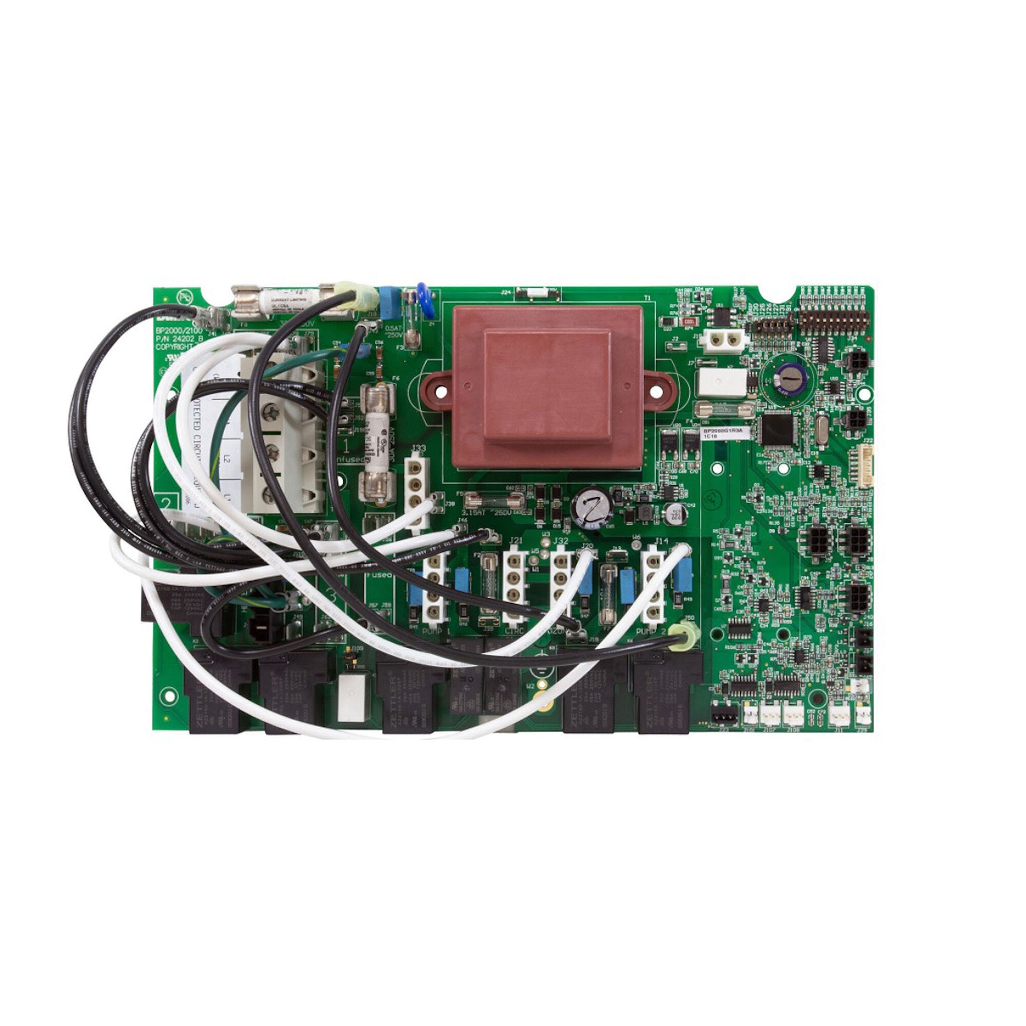
The Balboa BP2000G1 Circuit Board (59157-01) is the genuine Balboa Water Group main PCB for BP2000G1 spa control systems — and the current authorized replacement for the discontinued HydroQuip BP2000-M8 board. It is the top-tier member of Balboa’s BP2000 family, engineered for hot tubs that demand maximum pump flexibility, high heater output, and the latest smart home connectivity features.
Where simpler boards support one or two pumps, the BP2000G1 supports up to three pumps simultaneously — a 2-speed primary pump (Pump 1), a 2-speed secondary pump (Pump 2) direct from the main board, and a 2-speed Pump 3 via the X-P332 expander board — plus a dedicated blower circuit, an optional 120V or 240V circ pump, ozone, 12V lighting, and audio/video output. All of this is organized across 18 field-configurable software setups that cover the widest range of spa configurations in the BP-series lineup.
Compatible with the full range of Balboa TP-series graphic display panels — TP600, TP800, TP900, spaTouch™2/3, Icon spaTouch™, and Menued spaTouch™ — the BP2000G1 also supports Balboa Bluetooth Audio (bba™2/bba™3), CHROMAZON3™ LED color control, IR remote, Wi-Fi module, and Clim8zone™ (C8Z) heat pump connectivity.
⚠️ Important installation notes:
- Setups 5, 11, 12, 15, and 16 require BP2X-WIRE KIT (PN 30893) — order this separately if any of these setups apply to your spa.
- The X-P332 Expander Board (PN 59097) is required for Pump 3 and blower in most setups involving those devices.
- Circ pump and ozone are factory-configured at 120VAC but both can be converted to 240VAC together (they must remain the same voltage after any conversion).
🌟 Key Features
✅ Up to Three Pumps Simultaneously — Pump 1 (2-speed, 12A, heater pump in most setups), Pump 2 (2-speed/1-speed on main board J14), Pump 3 (2-speed/1-speed via X-P332 expander); the most output channels of any standard BP-series board
✅ 18 Field-Configurable Software Setups — Covers every combination of circ pump, 2-speed pumps, 1-speed pumps, blower, and pump count; ships in Setup 1 (no circ, P1 2-speed, P2 2-speed, P3 2-speed, no blower)
✅ Two Aux Panel Banks — Two independent auxiliary panel jacks (J5 Bank 1 and J8 Bank 2) with independently assignable buttons, supporting AX10, AX20, and AX40 auxiliary panels for maximum layout flexibility
✅ Smart Technology Platform — Supports bba™2/bba™3 Bluetooth Audio (integrated via TP800/TP900/spaTouch™; menu-controlled via TP600), CHROMAZON3™ LED color control, ControlMySpa Wi-Fi module, and IR remote module
✅ Clim8zone™ Heat Pump Compatible — AV output can be converted from 120VAC to 240VAC to support Clim8zone™ (C8Z) heat pump connectivity via J33; optional splitter PN 22934 allows simultaneous audio and C8Z
✅ spaTouch™3 Ready — Compatible with the latest spaTouch™3 touchscreen panel (v3.2+ for C8Z support), making this the most forward-compatible BP2000 replacement board
✅ GFCI Trip Detection — Built-in Class A GFCI trip detection (enabled in software via J109); freeze protection at 44°F (6.7°C); dual hi-limit monitoring; heater dry-detection; heater disable input (J29)
✅ 120V Circ Pump + Ozone — Factory-configured 120VAC circ pump and ozone outputs; both can be field-converted to 240VAC together (must remain same voltage); circ pump required as heater pump in Setups 7–14, 16, 17
✅ Genuine Balboa OEM PCB — Factory-new 59157-01 replacement PCBA with software M100_220 V65.0; correct relay ratings and firmware for BP2000G1 systems
✅ UL Listed — UL System Model BP20-BP2000G1-AU; designed for North American 240VAC/60Hz service
✅ 1-Year Manufacturer Warranty — Backed by Balboa Water Group’s standard 1-year limited warranty
🔧 Technical Specifications
| Specification | Value |
|---|---|
| Current Manufacturer Part Number | G1321 (formerly 59157-01) |
| Replacement PCBA Part Number | 59157-01 |
| System Part Numbers | 56377-05 (5.5kW 800 Incoloy), 56378-05 (5.5kW 825 Incoloy), 56379-05 (5.5kW Titanium), 56589-03 (4.0kW Titanium), 59415-01 (4.0kW 800 Incoloy) |
| Board Platform | BP2000G1 |
| Board Type | Main PCB / Control Board |
| UL System Model | BP20-BP2000G1-AU |
| Software Version | M100_220 V65.0 |
| Input Voltage | 240VAC, 50/60Hz |
| Maximum Service Amperage | 48A |
| Circuit Breaker Maximum | 60A maximum |
| Service Wiring | 4 wires: hot (black), hot (red), neutral (white), ground |
| Minimum Wire Gauge | #6 AWG copper, 90°C rated |
| Terminal Block Torque (TB1) | 27–30 in. lbs. (31.1–34.5 kg·cm) |
| GFCI Protection | Class A GFCI required |
| Pump 1 Output | 240VAC, 2-Speed (1-Speed in Setups 12, 14, 17), 12A max — heater pump in Setups 1–6, 15, 18 |
| Pump 1 Voltage | 110/220V, 1 or 2 speed, 12A max |
| Pump 2 Output | 240VAC, 2-Speed (1-Speed in Setups 5, 6, 11–14, 17, 18), 12A max — via J14 on main board |
| Pump 2 Voltage | 110/220V, 1 or 2 speed, 12A max |
| Pump 3 Output | 240VAC, 2-Speed (1-Speed in Setups 2, 5, 6, 8, 11–16; unused in Setups 3, 4, 9, 10, 17, 18), 12A max — via X-P332 expander board |
| Blower Output | 240VAC, 1-Speed, 4A max — via J14 and J43 jumper; unused in many setups |
| Circ Pump Output | 120VAC (convertible to 240V), 1-Speed, 2A max — heater pump in Setups 7–14, 16, 17 |
| Ozone Output | 120VAC (convertible to 240V), 0.5A max — slaved to circ pump in Setups 7–14, 16, 17; independent in Setups 1–6, 15, 18 |
| Circ + Ozone Voltage Rule | Both must be the same voltage (both 120V or both 240V); converting one converts both |
| Spa Light Output | 10VAC, On/Off, 2A max (shared with CHROMAZON3™) |
| A/V Output (audio only) | 120VAC, 4A max, always on |
| A/V + Clim8zone™ Output | 240VAC, 2A + 8A max (AV wire must be moved from Group 4 to Group 2) |
| Heater — 5.5kW | 5.5kW @ 240VAC (800 Incoloy or 825 Incoloy or Titanium) |
| Heater — 4.0kW | 4.0kW @ 240VAC (800 Incoloy or Titanium) |
| Heater Flow Requirement | Minimum 20 GPM through heater |
| Pump 2 + Pump 3 Amperage Rule | In Setups 5, 11, 12 (both on expander): Pump 2 + Pump 3 must not exceed 20A total |
| Expander Board | X-P332 (PN 59097) — required for Pump 3 and blower in applicable setups |
| BP2X-WIRE KIT | PN 30893 — required for Setups 5, 11, 12, 15, 16 |
| Software Setups | 18 (ships in Setup 1) |
| Aux Panel Banks | Bank 1 (J5, A1–A4) and Bank 2 (J8, A5–A8) — 8 assignable buttons total |
| Hi-Range Temperature | 80°F–104°F (26.7°C–40°C); default 100°F |
| Lo-Range Temperature | 50°F–99°F (10°C–37.2°C); default 70°F |
| Freeze Protection Threshold | 44°F (6.7°C); adjustable 39°F–54°F |
| Heater Kits (5.5kW) | 58083R16 (800 Incoloy), 58089R16 (825 Incoloy), 55624R16 (Titanium) |
| Heater Kits (4.0kW) | 58104R16 (800 Incoloy), 55625R16 (Titanium) |
| Temp Sensor Kit | 53605 |
| Fuse F6, F8 | 30A — PN 30136 |
| Fuse F4 | 2A — PN 26307 |
| Fuse F3 | 0.5A SLO — PN 26905 |
| Fuse F2, F7 | 10A — PN 26904 |
| Fuse F5 | 3.15A SLO — PN 26976 |
| Fuse F1 (Expander) | 30A — PN 30136 |
| Certifications | UL (BP20-BP2000G1-AU) |
| Warranty | 1 Year (Balboa Water Group) |
| Physical Dimensions | Please refer to manufacturer documentation or contact Parts4Tubs |
⚠️ US Voltage Note: This board is a North American UL-listed board designed for 240VAC / 60Hz service. Circ pump and ozone are factory-configured at 120VAC. Always confirm all equipment voltages before connecting.
🔗 Compatibility Guide
Systems This Board Replaces
| Part Number | Description |
|---|---|
| G1321 | Current Balboa manufacturer part number (replaces 59157-01) |
| 59157-01 | Balboa replacement PCBA — most recent production |
| 59157 | Balboa PCBA — earlier suffix |
| 56377-05 | System PN — 5.5kW 800 Incoloy (current) |
| 56377 / 56377-01 through -04 | Earlier system revisions |
| 56378-05 | System PN — 5.5kW 825 Incoloy |
| 56379-05 | System PN — 5.5kW Titanium |
| 56379 / 56379-01 | Earlier system revisions |
| 56589-03 | System PN — 4.0kW Titanium |
| 56589-01 / 56589-02 | Earlier system revisions |
| 59415-01 / 59415 | System PN — 4.0kW 800 Incoloy |
| 56380-03 | Earlier PCBA revision |
| 56380 / 56380-01 / 56380-02 | Earlier PCBA revisions |
| BP2000-G1 / BP2000G1 | Model designations |
| BP2000G1R1D | Chip/board designation |
| 56380R1A | Chip designation |
| 9297-010 | Cross-reference |
| 33-59157-K | Hydro-Quip kit number |
| 33-56380-K | Hydro-Quip kit number |
| G1321 | Alternate designation |
| 56689-03 | Coast Spas control system |
| 389286 | Cross-reference |
| 59-138-3055 | Distributor alternate reference (internal) |
Compatible Topside Control Panels
| Panel | Minimum Version | Notes |
|---|---|---|
| spaTouch™3 | Any version | v3.2+ for Clim8zone™ (C8Z) support |
| spaTouch™2 | Any version | v2.19+ for CHROMAZON3™; v2.36+ for C8Z |
| Icon spaTouch™ | Any version | v3.36+ for bba™2 fully integrated |
| Menued spaTouch™ | Any version | v2.8+ for bba™2 |
| TP900 | v3.1+ | v3.13+ for bba™ |
| TP800 | v3.1+ | v3.13+ for bba™; v4.11+ for bba™2 |
| TP700 | Compatible | See specific PN below |
| TP600 | v2.7+ | v2.12+ for bba™/bba™2 menu control; PNs 55673, 55676 (no overlay), 56046 (w/15ft cable) |
| TP500 / TP500S | Compatible | — |
| TP400T | Compatible | PNs 50260, 55701, 30-175-0260 |
| TP400W | Compatible | PNs 50259, 55702 |
ℹ️ All Balboa TP-series graphic display panels work with the BP2000G1 system. bba™2/bba™3 is integrated into TP800, TP900, and spaTouch™ panels. With TP600, use the “BT” menu entry to toggle bba™2/bba™3 power On/Off.
Compatible Spa Brands (Select Models)
| Brand | Details |
|---|---|
| Coast Spas | Control system 56689-03 |
| Spas using BP2000G1 systems | Any spa using a BP2000-G1 control system PN from the cross-reference list above |
⚠️ This board serves a wide range of hot tub brands wherever a BP2000G1 control system was installed. Always verify by matching the system part number or PCBA part number from the label inside the control box.
🎛️ Board Functions & Controls
Setup Reference Table (Ships in Setup 1)
| Setup # | Circ Pump | Pump 1 | Pump 2 | Pump 3 | Blower | Wire Kit Needed |
|---|---|---|---|---|---|---|
| 1 | None | 2-Speed | 2-Speed | 2-Speed | — | No |
| 2 | None | 2-Speed | 2-Speed | 1-Speed | — | No |
| 3 | None | 2-Speed | 2-Speed | — | 1-Speed | No |
| 4 | None | 2-Speed | 2-Speed | — | — | No |
| 5 | None | 2-Speed | 1-Speed | 1-Speed | 1-Speed | ✅ Yes — PN 30893 |
| 6 | None | 2-Speed | 1-Speed | 1-Speed | — | No |
| 7 | Prog. Filtration + Polling | 2-Speed | 2-Speed | 2-Speed | — | No |
| 8 | Prog. Filtration + Polling | 2-Speed | 2-Speed | 1-Speed | — | No |
| 9 | Prog. Filtration + Polling | 2-Speed | 2-Speed | — | 1-Speed | No |
| 10 | Prog. Filtration + Polling | 2-Speed | 2-Speed | — | — | No |
| 11 | Prog. Filtration + Polling | 2-Speed | 1-Speed | 1-Speed | 1-Speed | ✅ Yes — PN 30893 |
| 12 | Prog. Filtration + Polling | 1-Speed | 1-Speed | 1-Speed | 1-Speed | ✅ Yes — PN 30893 |
| 13 | Prog. Filtration + Polling | 2-Speed | 1-Speed | 1-Speed | — | No |
| 14 | Prog. Filtration + Polling | 1-Speed | 1-Speed | 1-Speed | — | No |
| 15 | None | 2-Speed | 2-Speed | 1-Speed | 1-Speed | ✅ Yes — PN 30893 |
| 16 | Prog. Filtration + Polling | 2-Speed | 2-Speed | 1-Speed | 1-Speed | ✅ Yes — PN 30893 |
| 17 | Prog. Filtration + Polling | 1-Speed | 1-Speed | — | 1-Speed | No |
| 18 | None | 2-Speed | 1-Speed | — | 1-Speed | No |
DIP Switch Functions (Switchbank S1)
| Switch | OFF Position | ON Position |
|---|---|---|
| A1 | Test Mode OFF (normal) | Test Mode ON |
| A2 | No 1 HS pump with heater | Add 1 HS pump with heater |
| A3 | No 2 HS pumps with heater | Add 2 HS pumps with heater |
| A4 | No 4 HS pumps with heater | Add 4 HS pumps with heater |
| A5 | Special Amperage Rule A | Special Amperage Rule B |
| A6 | Store settings (normal — must be OFF after final installation) | Memory Reset (used at power-up to restore factory settings) |
| A7 | 1-minute heater cooldown (electric heaters) | 5-minute heater cooldown (gas heaters) |
| A8–A10 | Not assigned | Not assigned |
ℹ️ DIP switches A2, A3, and A4 combine to set the number of high-speed pumps/blowers that can run before the heater is disabled: A2 only = 1; A3 only = 2; A2+A3 = 3; A4 = 4; all off = heater disabled with any high-speed device.
Key Jumpers
| Jumper | Function |
|---|---|
| J24 | Center 2 pins (230V) = heater at 240V; outer 2 pairs (115V) = heater at 120V |
| J29 | Heater disable input — if shorted, heater will not run; “J29” appears on panel at power-up |
| J91 | Real Time Clock Enable/Disable — do NOT short when TP panel can display time of day |
| J109 | GFCI Test/Trip Enable/Disable (must also be enabled in software) |
| J25, J26, J27 | Heater type settings — factory configured, do NOT change |
| J30 | Do Not Use |
| J31 | Not applicable on UL models (CE models only) |
| J43 to J13 | Required for Blower on J14 in Setups 3, 5, 9, 11, 12, 17, 18 |
Expander Board Wiring (X-P332 / PN 59097)
| Setup(s) | Expander Function |
|---|---|
| 1, 7 | 2-Speed Pump 3 |
| 2, 6, 8, 13, 14 | 1-Speed Pump 3 only |
| 15, 16 | 1-Speed Pump 3 AND 1-Speed Blower (with splitter + in-line fuse) |
| 5, 11, 12 | 1-Speed Pump 2 AND 1-Speed Pump 3 (Pump 2 + Pump 3 ≤ 20A total) |
| 3, 9 | 2-Speed Pump 2 |
| 17, 18 | 1-Speed Pump 2 |
| 4, 10 | Unused |
⚙️ Installation Requirements
⚠️ IMPORTANT: All electrical work must be performed by a licensed electrician in compliance with the National Electrical Code (NEC) Article 680 and all applicable local codes.
Pre-Installation Checklist
- [ ] Confirm existing board is a BP2000G1 system (check system PN or PCBA label inside control box)
- [ ] Note the current Setup number from the label inside the system lid
- [ ] Photograph all wiring, DIP switch positions, and jumper positions before removing old board
- [ ] Record circ pump and ozone wiring (120V or 240V)
- [ ] Check if Setups 5, 11, 12, 15, or 16 apply — if so, order BP2X-WIRE KIT PN 30893 before starting
- [ ] Check if X-P332 Expander Board (PN 59097) is installed — confirm its position
- [ ] Disconnect ALL power at the circuit breaker and GFCI before starting
- [ ] Allow capacitors to discharge — wait at least 5 minutes after power-off
Electrical Requirements
| Requirement | Specification |
|---|---|
| Supply Voltage | 240VAC / 60Hz |
| Maximum Service Amperage | 48A |
| Circuit Breaker Maximum | 60A |
| GFCI Protection | Class A GFCI required — NEC Article 680 |
| Service Wiring | 4 wires: hot (black), hot (red), neutral (white), ground |
| Minimum Wire Gauge | #6 AWG copper, 90°C rated |
| Terminal Torque (TB1) | 27–30 in. lbs. |
| Ground / Bonding | Equipment grounding and bonding required — NEC Article 680 |
| Dedicated Circuit | Required |
| Disconnect | Within line of sight of spa, minimum 5 ft from water (NEC) |
Post-Wiring Steps
- Set DIP switches to match original configuration (or spa manufacturer specification)
- Set Setup number to match original — enter Test Mode (A1 ON) to change Setup if needed
- Write Setup number on label inside system lid
- Verify J43 to J13 jumper position for Blower in Setups 3, 5, 9, 11, 12, 17, 18
- Verify circ pump and ozone wiring (J20 connection for 240V; Group 4 for 120V)
- Set J24 jumper for heater voltage (center = 240V)
- Set DIP A6 to OFF upon final installation
- Confirm TP panel version meets minimum requirements for bba™2, CHROMAZON3™, or C8Z features
💡 Tip: Write the Setup number on the label inside the system lid using a permanent marker before removing the old board — this is essential information for any future service technician.
🛡️ Safety Warnings
Electrical Safety:
- ⚠️ ALWAYS disconnect ALL power at the breaker and GFCI before any work
- ⚠️ Installation MUST be performed by a licensed electrician only
- ⚠️ This board requires 240VAC / 60Hz 4-wire service — verify before connecting
- ⚠️ Class A GFCI protection is mandatory per NEC Article 680
- ⚠️ Use copper conductors ONLY — #6 AWG minimum, 90°C rated
- ⚠️ A dedicated circuit and disconnect within line of sight of spa are required by NEC
- ⚠️ Equipment grounding and bonding (NEC Article 680) is mandatory
Board-Specific Warnings:
- ⚠️ Setups 5, 11, 12, 15, 16 require BP2X-WIRE KIT PN 30893 — do not attempt to use these setups without this kit
- ⚠️ Circ pump and ozone MUST be the same voltage — converting one converts both; mixed voltages on J21/J32 will damage equipment
- ⚠️ AV output MUST be rewired from 120V to 240V (move J38 from Group 4 to Group 2) before connecting Clim8zone™ heat pump
- ⚠️ J25, J26, J27 are factory configured — do NOT change these jumpers
- ⚠️ DIP Switch A6 must be set to OFF upon final installation — leaving it ON causes factory reset on every power-up
- ⚠️ Pump 2 + Pump 3 must not exceed 20A total in Setups 5, 11, 12 — configure each pump for appropriate amperage
- ⚠️ Setting DIP switches or jumpers incorrectly will cause abnormal behavior or component damage
- ⚠️ Test Mode (A1 ON) allows HIGH VOLTAGE access — ONLY for trained service technicians
Post-Installation:
- ⚠️ Test GFCI function, hi-limit sensors, and all pump circuits before use
- ⚠️ Verify heater operates correctly in active setups
- ⚠️ Check for error codes on initial startup
🔍 Error Codes & Troubleshooting
Common Display Messages
| Code | Meaning | First Action |
|---|---|---|
| dr / dY | Dry heater — possible flow issue | Check water level, filter, pump prime, flow rate ≥ 20 GPM through heater |
| J29 | Heater disable switch shorted at J29 | Check J29 connection; press any button to dismiss |
| Sn | Sensor fault | Check Sensor A and B connections; inspect sensor cable |
| – – – | Water temperature unknown | Normal — wait 2 minutes with Pump 1 running |
| CrC | Firmware checksum error | Power cycle; if repeated, contact dealer |
| SnA/SnB | Individual sensor fault | Isolate by swapping Sensor A and B positions |
Troubleshooting Quick Reference
| Symptom | Likely Cause | First Step |
|---|---|---|
| No heat | Pump A2/A3/A4 heat disable, low flow, or wrong heater voltage | Check DIP A2–A4; verify 20 GPM flow; confirm J24 heater jumper |
| GFCI trips immediately | Wiring fault | Disconnect all outputs; have licensed electrician diagnose |
| Pump 3 not responding | Expander not connected, wrong setup, or wrong wiring | Verify X-P332 connected at J107/J108; confirm Setup allows Pump 3 |
| Blower not responding | Wrong setup, wrong J43 wiring, or expander issue | Verify J43 to J13 jumper; confirm Setup includes blower |
| A6 resets settings on power-up | A6 left ON after installation | Set DIP A6 to OFF upon final installation |
| Circ pump not running | A9/A10 settings, wrong setup, or voltage mismatch | Confirm circ pump setup selection (Setups 7–16 include circ); check J21 and J20 wiring |
| Ozone not running | Voltage mismatch with circ pump | Confirm W2/ozone wiring matches circ pump voltage |
| C8Z heat pump not working | AV wire not converted to 240V | Move J38 from Group 4 to Group 2; verify C8Z connected to J33 |
🎯 Ideal Applications
| Application | Suitability | Notes |
|---|---|---|
| ♨️ BP2000G1 system — direct board replacement | ✅ Exact replacement | Match system PN; restore Setup number and DIP settings |
| ♨️ Coast Spas (56689-03) | ✅ Compatible | Coast Spas control system confirmed compatible |
| ♨️ Any BP2000G1-equipped spa needing 3 pumps | ✅ Maximum pump output | Pump 1 + Pump 2 on main board + Pump 3 via X-P332 expander |
| ♨️ Spa needing circ pump + 2 or 3 jet pumps | ✅ Setups 7–16 | Circ pump serves as heater pump in these setups |
| ♨️ Spa with Clim8zone™ heat pump | ✅ C8Z supported | AV must be rewired to 240V; spaTouch™3 v3.2+ recommended |
| ♨️ Spa needing CHROMAZON3™ LED lighting | ✅ Supported | spaTouch™2 v2.19+ or spaTouch™3 recommended |
| ♨️ Spa with Bluetooth audio (bba™2/bba™3) | ✅ Integrated | Via TP800/TP900/spaTouch™; menu-controlled via TP600 |
| ♨️ Spa needing 1 or 2 pumps only | ✅ Setups 3, 4, 9, 10, 17, 18 | Board is fully capable; simpler setups use fewer outputs |
❓ Frequently Asked Questions
Q: How do I know if this board is right for my spa? A: Locate the system part number label inside your spa’s control box. If it shows any of the BP2000G1 system PNs (56377, 56378, 56379, 56589, 59415 — any revision) or PCBA numbers (59157, 56380 — any revision), this is the correct replacement board. Contact Parts4Tubs with your label details if uncertain.
Q: This was shown as a replacement for the discontinued HydroQuip BP2000-M8. Will it work? A: Yes. The BP2000G1 (59157-01) is the current authorized replacement for the discontinued HydroQuip BP2000-M8 board. The board is functionally compatible, though DIP switch settings and component voltage wiring may need to be verified and adjusted to match your original spa configuration.
Q: Do I need the BP2X-WIRE KIT (PN 30893)? A: Only if your spa uses Setup 5, 11, 12, 15, or 16 — the five setups that combine a blower with two pumps on the expander board, or three pumps simultaneously. For all other setups, the wire kit is not required. If you are unsure of your spa’s setup, check the label inside the system lid or contact Parts4Tubs.
Q: What is the X-P332 Expander Board and do I need it? A: The X-P332 (PN 59097) is a daughter board that provides the Pump 3 output relay. It is required in any setup that includes Pump 3 or uses 2-Speed Pump 2 from the expander (Setups 3, 9). If your spa currently uses Pump 3 or Pump 2 from an expander board, the existing X-P332 can typically be reused. Contact Parts4Tubs if you need to order one.
Q: How do I change the setup number on this board? A: Enter Test Mode by setting DIP Switch A1 to ON while the system is running. Use your topside panel to navigate to the Setup screen, select the desired Setup, confirm, and let the spa restart. With TP600/TP400 panels, follow the button sequence in the tech sheet. Set A1 back to OFF when finished. Write the new Setup number on the label inside the system lid.
Q: Can the circ pump run at 240V? A: Yes — both the circ pump (J21) and ozone (J32) can be converted from the factory-default 120VAC to 240VAC by connecting J20 to Group 2 (instead of Group 4). Both outputs must always be the same voltage — converting one changes both.
Q: Do I need a licensed electrician to install this? A: Yes. NEC Article 680 and most local jurisdictions require a licensed electrician for all hot tub electrical work including circuit board replacement. A permit may also be required.
Q: What warranty is included? A: Balboa Water Group provides a 1-year limited warranty against defects in materials and workmanship. Circuit boards are non-returnable once installed. Contact Parts4Tubs for warranty claim assistance.
📥 Downloads & Resources
📄 Balboa BP2000G1 Tech Sheet — Current (Official Manufacturer PDF) — Complete specifications, 18-setup wiring diagram, DIP switch definitions, jumper descriptions, expander board wiring, fuse part numbers, heater kit numbers, panel configuration tables (TP600/TP800/TP900), and full configuration options reference
⭐ Why Choose the Balboa BP2000G1 (59157-01)?
✅ Most Capable Standard BP2000 Board — Three jet pumps, blower, circ pump, ozone, lighting, and audio/video in a single board + expander — the most output channels of any BP2000G1 configuration
✅ 18 Software Setups — Covers every pump and blower combination a spa manufacturer is likely to use; one board for the widest range of BP2000G1 spa configurations
✅ Latest Smart Technology Support — spaTouch™3, CHROMAZON3™, bba™2/bba™3 Bluetooth Audio, Clim8zone™ heat pump, Wi-Fi module, and IR remote all supported from a single board
✅ Genuine Balboa OEM Component — Correct relay ratings, firmware version V65.0, and UL listing for BP2000G1 systems; not an aftermarket substitute
✅ UL Listed — Certified for North American 240VAC/60Hz spa electrical systems
✅ GFCI Trip Detection — Built-in Class A GFCI trip, freeze protection, dual hi-limit monitoring, and heater dry detection for maximum safety
✅ Two Aux Panel Banks — Eight independently assignable aux buttons across two banks (J5 and J8) give unmatched flexibility for custom spa control layouts
✅ 1-Year Manufacturer Warranty — Backed by Balboa Water Group
🤝 Why Buy From Parts4Tubs?
✅ Fast US shipping on in-stock Balboa spa parts
✅ Spa specialists available for BP2000G1 setup selection and wiring guidance
✅ Competitive pricing on genuine Balboa OEM circuit boards
✅ Full warranty support — we assist with Balboa warranty claims
✅ Easy returns within 30 days on eligible non-electrical items
✅ Related parts available — X-P332 expander board, BP2X-WIRE KIT (PN 30893), TP600/TP800/TP900 topside panels, heater kits, sensors, fuses, and more
✅ Expert guidance on BP2000G1 setup selection for your specific spa configuration
✨ Summary
The Balboa BP2000G1 Circuit Board (59157-01) — the current authorized replacement for discontinued BP2000-M8 and earlier BP2000G1 boards — delivers three pump outputs, a blower, optional circ pump, ozone, 12V lighting, and audio/video across 18 field-configurable software setups. With UL listing, bba™2/bba™3 Bluetooth Audio, CHROMAZON3™, spaTouch™3, and Clim8zone™ heat pump compatibility built in, it is the most future-ready standard BP2000 PCB available. Note: Setups 5, 11, 12, 15, and 16 require BP2X-WIRE KIT (PN 30893); Pump 3 requires the X-P332 Expander Board (PN 59097). Backed by a 1-year Balboa warranty. Order from Parts4Tubs today.

Parts4Tubs is proud to be a Balboa Authorized Online Seller - make sure you only buy genuine Balboa parts from trusted sources.
Parts4Tubs is proud to be a Balboa Authorized Online Seller - make sure you only buy genuine Balboa parts from trusted sources.
Finding and identifying a replacement Hot Tub Circuit Board (PCB)
If you are looking to replace a failed PCB on your Hot Tub’s spa pack, then quite often identifying the part that you need can be the hardest thing.
Firstly, you are looking for a model number on the actual circuit board itself. Having the model or serial of your hot tub is not going to help at this point, you need to find the number on the PCB itself.
Now, with certain brands of PCB, the number of the replacement PCB that you need is not going to match identically the one you are replacing. Why is that I hear you ask?
Well, normally, it is an updated version. This means that it might have updated firmware on the PCB or be a later revision. Normally, this means that the part number would be slightly different. This is usually indicated with a “12345678 -x” at the end of that part number where x indicated a firmware revision.
In some cases, there will be some following letters on the part number of the circuit board, “12345678 -x MAS” this can indicate that the PCB was used for an OEM meaning it was produced for a certain hot tub manufacturer and the letters identify the manufacturer.
This means if you source an original PCB, it will not have the letters, but will in most cases work just fine.
It can be confusing I know!
What if you can’t find a model number?
If you can’t find a model number on the PCB itself, then you need to look for a model number on the spa pack. Normally, there is a sticker on the outside of the spa pack that tells you the current ratings and input voltages etc and this will have a model number.
In general, most spa packs in the USA are manufactured by Balboa, Hydro-Quip, ACC or Gecko. I know I am generalising here, but if you have a spa pack that has the brand of your hot tub on, it will be an OEM so the key is identifying who made the original box.
From there, you can normally find an original PCB that you will be able to switch out.
For example, the Balboa VS (value series) is a very popular spa pack that has been used by multiple hot tub manufacturers under their own brand names. Whatever they have called it, strip it back and it is still a Balboa VS.
Visual Inspection
One of the most important things you can do when you are looking for a replacement is to visually inspect the PCB that you have versus the picture online of the replacement you are considering. They need to look the same even if there are the differences in firmware revisions or OEM part numbers, you should be visually replacing a PCB that looks like the one you have.
Configuring a replacement Hot Tub Circuit Board (PCB)
When you get a new PCB, you are more than likely going to need to configure it. Most PCBs have a number of different modes and setups that the can operate in. For this, you will need to manual or spec sheet to guide you.
For things like DIP switches, most of the time you can copy the settings from your original circuit board. You are looking for things like setting the voltage as a lot of PCBs can be configured to run on both 115V and 230V.
You may need to move jumpers or even wires to configure voltages – the key here is that you read the schematic and don’t expect the PCB to just work out of the box – it usually doesn’t.
Troubleshooting a Hot Tub Circuit Board (PCB)
Here are some common things you will see when you replace a PCB on a hot tub.
You press the buttons on the topside control and they don’t control the right parts (pumps or blower etc) – this is a mode configuration thing and you will either need to change some DIP switches on the PCB or an internal or low level programming mode on the topside control. Check the manual for how to do this.
You turn on the hot tub and it trips the breaker – it is not common for a new PCB to fail out of the box (I have not seen one yet!) However, a common mistake is that the voltage has not been set correctly. If it is set for 115V and then you try and turn it on, the current draw will be a lot more (twice) than expected and the breaker will trip.
To check this, unplug all of your kit – heater, pumps, blower and then turn on the PCB. If it trips with nothing plugged in, usually the voltage is incorrectly set and what is happening is that live current is being sent to the ground – because you have 4 wires into the PCB rather than 3. Current on the ground loop causes the trip. Check the settings to make sure it is configures for 230V.
It might not trip until you physically turn on a pump or a blower. As mentioned, if the pack is set to 115V and your pump is meant for 230V, it will draw twice the current at half the voltage and trip your breaker. Check the manual for info on how to set the voltage.
| Brand | Balboa |
|---|
Related products
Out of stock
Gecko Heating
$94.51
Hydro-Quip Spa Controls
Hydro-Quip Outdoor Series 5.5kW 230V Flow Thru Heater 26-0053-F-M7-KS
$185.33
Sundance Circuit Boards
$590.80
Hydro-Quip Spa Controls
Hydro-Quip 6000 Series Spa Control Flow Thru Heater CS6200Y-U-WP
$672.91
Out of stock
CTI Circuit Boards
$773.27
Watkins Topside Controls
$469.22
Spa Accessories
$686.40
Gecko Heating
$112.64