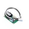
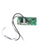


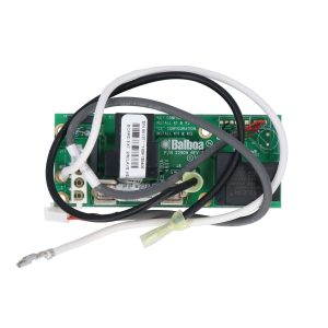

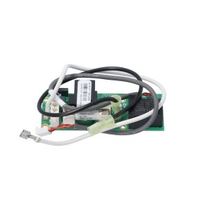
Balboa X-P332 VS Expander Board — 55137 (VS520 / BP7 / BP501 Systems, 2-Speed Pump 2)
$88.13
Circuit Board, Expander Kit, Balboa VS520Z/525Z/520SZ/520DZ/523DZ, BP7 & BP501 Systems 2-Speed Pump, w/30 Amp Fuse, w/Cables
11 in stock
Fast dispatch
Order in
--:--:--
for shipping today
🔌 Balboa X-P332 VS Expander Board — 55137 (VS520 / BP7 / BP501 Systems, 2-Speed Pump 2)
Add a second 2-speed pump to your Balboa VS520 or BP-series spa control system with this genuine OEM expander board.
⚠️ IMPORTANT — THIS IS AN EXPANDER (DAUGHTER) BOARD, NOT A STANDALONE CONTROL BOARD
The Balboa 55137 (X-P332) cannot operate on its own. It is a secondary circuit board that mounts inside the spa control box alongside a compatible main board to provide an additional 2-speed pump output.
You must already have — or be installing — a compatible Balboa main board (VS520Z, VS525Z, VS520SZ, VS520DZ, VS523DZ, BP7, or BP501 series) for this expander to function.
If you are looking for a complete main control board, please browse the main circuit board section or contact Parts4Tubs for guidance.
📋 Product Overview
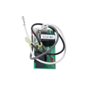
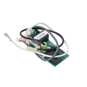
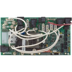
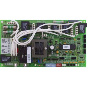
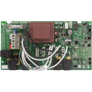
The Balboa X-P332 Expander Board (Part Number 55137, PCB reference 22909) is a genuine OEM daughter board manufactured by Balboa Water Group® that adds a second 2-speed pump output to compatible VS520-series and BP-series spa control systems. It connects directly to the main control board inside the spa pack enclosure via a dedicated wiring harness.
The VS520Z and related systems require this expander board any time a 2-speed Pump 2 is part of the spa’s configuration — the main board alone cannot drive a 2nd 2-speed pump without it. The 55137 kit includes the expander board, 30A fuse, and all required connecting cables, providing a complete, ready-to-install solution.
Balboa Water Group has designated the G1920 as the current production successor to the 55137. Both versions provide the same 2-relay, 2-speed pump expansion function. Parts4Tubs stocks whichever current version Balboa ships.
⚠️ CRITICAL SAFETY WARNING — LPI501 SYSTEMS: The 55137 / X-P332 expander board must NOT be used as a replacement for part number 56710 / X-P3322 in Balboa LPI501 control systems. Installing this board in an LPI501 system could result in fire and damage to electrical components. Always verify your main board model before ordering.
✨ Key Features
- ✅ Genuine Balboa OEM Expander Board — Part number 55137, PCB reference 22909 Rev B, model X-P332; manufactured by Balboa Water Group®
- ✅ Adds Second 2-Speed Pump Output — Provides the Pump 2 high-speed and low-speed relay outputs needed for a 2nd jet pump; not available on the VS520Z main board alone
- ✅ 2-Relay Design — Dedicated high-speed and low-speed relay pair for full 2-speed pump control; 12A max load
- ✅ 30A Fuse Included — Board kit ships with the required 30A fuse for pump output protection
- ✅ Cables Included — All connecting cables for wiring to the compatible main board are included in the kit
- ✅ Compatible with VS520, BP7, and BP501 Systems — Works across the full range of VS520-series systems and BP7/BP501 aftermarket control systems
- ✅ PDF-Documented Integration — Installation and wiring positions are documented in the official Balboa VS520Z Tech Sheet (System PN 55601)
- ✅ 1-Year Manufacturer’s Warranty — Backed by Balboa Water Group’s 1-year limited warranty
⚙️ Technical Specifications
| Specification | Value |
|---|---|
| Manufacturer Part Number | 55137 |
| PCB Reference | 22909 Rev B |
| Board Model Name | X-P332 |
| Current Successor Part | G1920 |
| Board Type | Expander / Daughter Board — NOT standalone |
| Function | Adds 2nd 2-speed pump (Pump 2) output |
| Number of Relays | 2 (high speed + low speed) |
| Max Load per Relay | 12A |
| Included Fuse | 30A (F30A 480V) |
| Cables Included | Yes — full wiring harness included |
| System Voltage | Matches host system (120VAC or 240VAC / 60Hz) |
| Mounting Hardware | Not included — order X-Mount-P kit (PN 53933) separately if needed |
| Warranty | 1 year (Balboa Water Group manufacturer’s warranty) |
⚠️ This expander board must be used only with compatible Balboa main boards. Operating voltage matches the host system. Do not install without verifying main board compatibility first.
🔗 Compatibility Guide
Compatible Main Control Systems
| System / Board | Description |
|---|---|
| VS520Z | Balboa Value Series VS520Z |
| VS525Z | Balboa Value Series VS525Z |
| VS520SZ | Balboa Value Series VS520SZ |
| VS520DZ | Balboa Value Series VS520DZ |
| VS523DZ | Balboa Value Series VS523DZ |
| BP7 | Balboa BP7 aftermarket replacement system (G4361 / G5361 family) |
| BP501 | Balboa BP501 series systems |
| BP2000 | Balboa BP2000 systems |
Associated Part Numbers
| Number | Type |
|---|---|
| G1920 | Current Balboa production successor to 55137 |
| 22909 | PCB board reference number (printed on board) |
| X-P332 | Board model name |
| 33-55137-K | Kit variant |
| 33-0029 / 33-0029C-K | Alternate kit references |
| 3-60-0087 | Alternate catalog reference |
| 3-00-5012 | Alternate catalog reference |
| 446621 | Legacy alternate number |
Optional Accessory
| Part Number | Description |
|---|---|
| 53933 | X-Mount-P Mounting Kit — required only if mounting hardware is not already present in the control box |
⚠️ Incompatible System — Do NOT Use This Board
| Part Number | System | Reason |
|---|---|---|
| 56710 / X-P3322 | LPI501 Systems | ❌ This board is NOT a replacement for 56710 in LPI501 systems — fire and equipment damage risk |
🎛️ How This Expander Board Works
The X-P332 is a secondary relay board that physically mounts inside the spa pack control box and connects to the main VS500Z/VS520Z PCB via dedicated wiring. Once connected, the main board uses the expander’s two relays to control the high-speed and low-speed outputs of Pump 2.
Connection Points (per Official Balboa VS520Z Tech Sheet)
| Expander Terminal | Connected To | Function |
|---|---|---|
| J1 (Expander) | J1 (Main Board) | Data/control signal from main board |
| W1 (Expander) | W1 (Main Board) | Power connection |
| J7 (Expander) | J7 (Main Board) | Relay output wiring |
| J6 (Expander) | J6 (Main Board) | Relay output wiring |
| F30A Fuse | Internal | 30A fuse protects Pump 2 output |
Relay Outputs
| Relay | Function | Max Load |
|---|---|---|
| Relay 1 | Pump 2 — High Speed | 12A |
| Relay 2 | Pump 2 — Low Speed | 12A |
Main Board Alert (from Official Balboa Tech Sheet)
ℹ️ Per the Balboa VS520Z Tech Sheet: “2-speed Pump 2 is required, uses X-P332 expander board. To add Blower or 1-speed Pump 3, use J17/26 and 1-button Aux Panel.”
ℹ️ PCBA Rev D & E main boards: A black jumper on the main board (J1) is required and must not be removed. This is factory-installed on current revision main boards.
🔧 Installation Requirements
⚠️ IMPORTANT: Installation must be carried out by a licensed electrician in compliance with NEC (National Electrical Code) Article 680 and all applicable local codes.
Pre-Installation Checklist
- [ ] Confirm your main board is compatible: VS520Z, VS525Z, VS520SZ, VS520DZ, VS523DZ, BP7, BP501, or BP2000
- [ ] Confirm your system is NOT an LPI501 — this board cannot be used in LPI501 systems
- [ ] Disconnect all power at the breaker and disconnect box before starting
- [ ] Photograph existing wiring inside the control box before making any connections
- [ ] Allow capacitors to discharge — wait at least 5 minutes after power-off
- [ ] Verify mounting hardware is present in control box; if not, order X-Mount-P kit (PN 53933) separately
- [ ] On VS520Z main boards Rev D & E: confirm black jumper at J1 is present and in place
Electrical Requirements
| Requirement | Specification |
|---|---|
| Supply Voltage | Matches main board system (120VAC or 240VAC / 60Hz) |
| Max Pump 2 Load | 12A per relay |
| Fuse | 30A included in kit |
| GFCI Protection | Required — Class A GFCI per NEC Article 680 (provided by main system) |
| Ground Connection | Equipment grounding and bonding per NEC Article 680 (through main system) |
💡 Tip: Photograph all connections before and after installation. Follow the wiring diagram on the back of your spa pack cover for the exact connection positions specific to your system’s setup.
⚠️ Safety Warnings
- ⚠️ This is NOT a standalone board — it only operates when correctly connected to a compatible main control board
- ⚠️ DO NOT install in LPI501 systems — this board is not compatible with 56710/X-P3322 from LPI501 systems; doing so creates a fire and component damage risk
- ⚠️ ALWAYS disconnect all power at the breaker and disconnect box before any work
- ⚠️ Installation by a licensed electrician only — required by NEC Article 680 and most local codes
- ⚠️ Do not exceed 12A per relay — overloading the relay outputs will cause relay failure or fire risk
- ⚠️ Do not remove the 30A fuse — this fuse protects the pump 2 output circuit
- ⚠️ On VS520Z PCBA Rev D/E main boards: do not remove the black jumper at J1 — it is required for proper expander board operation
- ⚠️ If mounting hardware is absent from control box, order X-Mount-P kit (53933) before installation — do not force-mount the board without proper hardware
🎯 Ideal Applications
| Application | Suitability | Notes |
|---|---|---|
| ♨️ VS520Z / VS520SZ spa — adding 2nd pump | ✅ Required component | The VS520 series needs this board to run a 2-speed Pump 2 |
| ♨️ BP7 system — enabling Pump 2 output | ✅ Compatible | BP7 tech sheet confirms X-P332 as Pump 2 expander |
| ♨️ BP501 system — enabling Pump 2 output | ✅ Compatible | Confirmed compatible with BP501 series |
| ♨️ Replacing a failed 55137 expander board | ✅ Direct replacement | Same function; G1920 is current successor |
| ♨️ LPI501 system (using 56710 / X-P3322) | ❌ NOT compatible | Fire and equipment damage risk — do not use |
❓ Frequently Asked Questions
Q: Can this board work on its own to control my spa? A: No. The 55137 / X-P332 is a daughter board — it mounts inside the control box and connects to a compatible Balboa main board (VS520Z, BP7, BP501, etc.) to add a second 2-speed pump output. It cannot function independently.
Q: How do I know if my spa needs this expander board? A: If your spa has two jet pumps and the second pump is 2-speed, and your main board is a VS520Z, VS520SZ, VS520DZ, VS523DZ, VS525Z, BP7, BP501, or BP2000, your system uses this expander board to drive Pump 2. If your existing expander board has failed or was not originally included, this is the replacement.
Q: What’s the difference between the 55137 and the G1920? A: The G1920 is Balboa’s current production replacement for the 55137. They serve the same function — both are X-P332 style 2-relay expander boards for VS520/BP7/BP501 systems. Parts4Tubs will supply whichever current version Balboa ships.
Q: My system is an LPI501 — can I use this board to replace the 56710? A: No. The 55137/X-P332 must NOT be used in LPI501 systems as a replacement for the 56710/X-P3322. This substitution creates a fire and electrical damage risk. Contact Parts4Tubs to identify the correct board for your LPI501 system.
Q: Does the kit include all the cables I need? A: Yes — the 55137 kit includes the expander board, 30A fuse, and all required connecting cables for the main board interface. Mounting hardware (X-Mount-P kit, PN 53933) is sold separately and is only needed if hardware isn’t already present in your control box.
Q: Do I need a licensed electrician to install this? A: Yes. NEC Article 680 and most local codes require a licensed electrician for all hot tub electrical work. This board is installed inside the live high-voltage control box of the spa.
Q: What warranty is included? A: Balboa Water Group’s standard 1-year manufacturer’s limited warranty. Circuit boards are non-returnable after installation except for verified warranty defects. Improper installation or use in an incompatible system voids the warranty.
🏆 Why Choose the Balboa X-P332 55137 Expander Board
- ✅ Genuine Balboa OEM Board — Manufactured by Balboa Water Group to original production standards
- ✅ Complete Kit — Board, 30A fuse, and all cables included — nothing extra to source
- ✅ PDF-Documented Wiring — Connection positions fully documented in official Balboa VS520Z and BP7 tech sheets
- ✅ Broad System Coverage — Compatible with VS520Z, VS525Z, VS520SZ, VS520DZ, VS523DZ, BP7, BP501, and BP2000 systems
- ✅ 1-Year Manufacturer’s Warranty — Balboa Water Group warranty coverage
🤝 Why Buy from Parts4Tubs
- ✅ US-based company with knowledgeable local support
- ✅ Fast US shipping
- ✅ Expert technical advice from spa specialists who know Balboa VS and BP systems
- ✅ Competitive pricing on genuine OEM parts
- ✅ Full manufacturer warranty support
- ✅ Help identifying the correct expander board for your system — contact us with your main board part number
✨ Summary
The Balboa X-P332 Expander Board (55137) is a genuine OEM daughter board that adds a 2nd 2-speed pump output to compatible Balboa VS520-series and BP7/BP501/BP2000 spa control systems. With 2 relays rated at 12A max, a 30A fuse, and all connecting cables included, this kit provides everything needed to enable Pump 2 in systems that require it. It is not a standalone board and requires a compatible main control board already installed. Note: this board must NOT be used in LPI501 systems as a substitute for the 56710/X-P3322. The G1920 is the current Balboa production successor to the 55137.
Finding and identifying a replacement Hot Tub Circuit Board (PCB)
If you are looking to replace a failed PCB on your Hot Tub’s spa pack, then quite often identifying the part that you need can be the hardest thing.
Firstly, you are looking for a model number on the actual circuit board itself. Having the model or serial of your hot tub is not going to help at this point, you need to find the number on the PCB itself.
Now, with certain brands of PCB, the number of the replacement PCB that you need is not going to match identically the one you are replacing. Why is that I hear you ask?
Well, normally, it is an updated version. This means that it might have updated firmware on the PCB or be a later revision. Normally, this means that the part number would be slightly different. This is usually indicated with a “12345678 -x” at the end of that part number where x indicated a firmware revision.
In some cases, there will be some following letters on the part number of the circuit board, “12345678 -x MAS” this can indicate that the PCB was used for an OEM meaning it was produced for a certain hot tub manufacturer and the letters identify the manufacturer.
This means if you source an original PCB, it will not have the letters, but will in most cases work just fine.
It can be confusing I know!
What if you can’t find a model number?
If you can’t find a model number on the PCB itself, then you need to look for a model number on the spa pack. Normally, there is a sticker on the outside of the spa pack that tells you the current ratings and input voltages etc and this will have a model number.
In general, most spa packs in the USA are manufactured by Balboa, Hydro-Quip, ACC or Gecko. I know I am generalising here, but if you have a spa pack that has the brand of your hot tub on, it will be an OEM so the key is identifying who made the original box.
From there, you can normally find an original PCB that you will be able to switch out.
For example, the Balboa VS (value series) is a very popular spa pack that has been used by multiple hot tub manufacturers under their own brand names. Whatever they have called it, strip it back and it is still a Balboa VS.
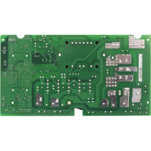
Visual Inspection
One of the most important things you can do when you are looking for a replacement is to visually inspect the PCB that you have versus the picture online of the replacement you are considering. They need to look the same even if there are the differences in firmware revisions or OEM part numbers, you should be visually replacing a PCB that looks like the one you have.
Configuring a replacement Hot Tub Circuit Board (PCB)
When you get a new PCB, you are more than likely going to need to configure it. Most PCBs have a number of different modes and setups that the can operate in. For this, you will need to manual or spec sheet to guide you.
For things like DIP switches, most of the time you can copy the settings from your original circuit board. You are looking for things like setting the voltage as a lot of PCBs can be configured to run on both 115V and 230V.
You may need to move jumpers or even wires to configure voltages – the key here is that you read the schematic and don’t expect the PCB to just work out of the box – it usually doesn’t.
Troubleshooting a Hot Tub Circuit Board (PCB)
Here are some common things you will see when you replace a PCB on a hot tub.
You press the buttons on the topside control and they don’t control the right parts (pumps or blower etc) – this is a mode configuration thing and you will either need to change some DIP switches on the PCB or an internal or low level programming mode on the topside control. Check the manual for how to do this.
You turn on the hot tub and it trips the breaker – it is not common for a new PCB to fail out of the box (I have not seen one yet!) However, a common mistake is that the voltage has not been set correctly. If it is set for 115V and then you try and turn it on, the current draw will be a lot more (twice) than expected and the breaker will trip.
To check this, unplug all of your kit – heater, pumps, blower and then turn on the PCB. If it trips with nothing plugged in, usually the voltage is incorrectly set and what is happening is that live current is being sent to the ground – because you have 4 wires into the PCB rather than 3. Current on the ground loop causes the trip. Check the settings to make sure it is configures for 230V.
It might not trip until you physically turn on a pump or a blower. As mentioned, if the pack is set to 115V and your pump is meant for 230V, it will draw twice the current at half the voltage and trip your breaker. Check the manual for info on how to set the voltage.
| Brand | Balboa |
|---|
Related products
Balboa Circuit Boards
Balboa GS500Z Spa Circuit Board — 54510 (Export / 50Hz International)
$266.93

Balboa Circuit Boards
$399.00
Out of stock
Balboa Circuit Boards
Balboa EL2001 Mach 3 Spa Circuit Board — G1223 (53974-05) — Multi-Pump 240V ML-Series Control System
$381.94
Balboa Circuit Boards
Balboa 1000LE Spa Circuit Board — 52491 (Duplex Digital, Pressure Switch)
$252.58
Out of stock
Balboa Circuit Boards
$561.60
Balboa Circuit Boards
Balboa D1SR Spa Circuit Board — 51485 (Dimension One Serial Deluxe)
$267.69
Out of stock
Balboa Circuit Boards
$302.93
Balboa Circuit Boards
$306.33