

Balboa VS501SZ Spa Circuit Board — 54378-03 — Dual-Voltage 120V/240V Serial Standard Spa Control
$276.56
Out of stock
Want to be notified when this product is back in stock?
Fast dispatch
Order in
--:--:--
for shipping today
⚡ Balboa VS501SZ Spa Circuit Board — 54378-03 — Dual-Voltage 120V/240V Serial Standard Spa Control
Professional-grade replacement board for reliable VS501SZ spa control and performance.
⚠️ IMPORTANT — PLEASE READ BEFORE ORDERING
- ⚠️ CHIP NUMBER WARNING — TWO VISUALLY SIMILAR CHIPS: This board (54378-03) is associated with chip INFI07R* (with the letter “I” as the 4th character). A closely related but different board carries chip INF107R* (with the number “1” as the 4th character). These chips look nearly identical on the label. Confirm your chip character by character before ordering.
- Identify your board by chip number. Do not order based on appearance alone.
- Dual-voltage system — 120V or 240V. This board supports both 120VAC and 240VAC service depending on how your spa is wired. Verify your supply voltage before ordering.
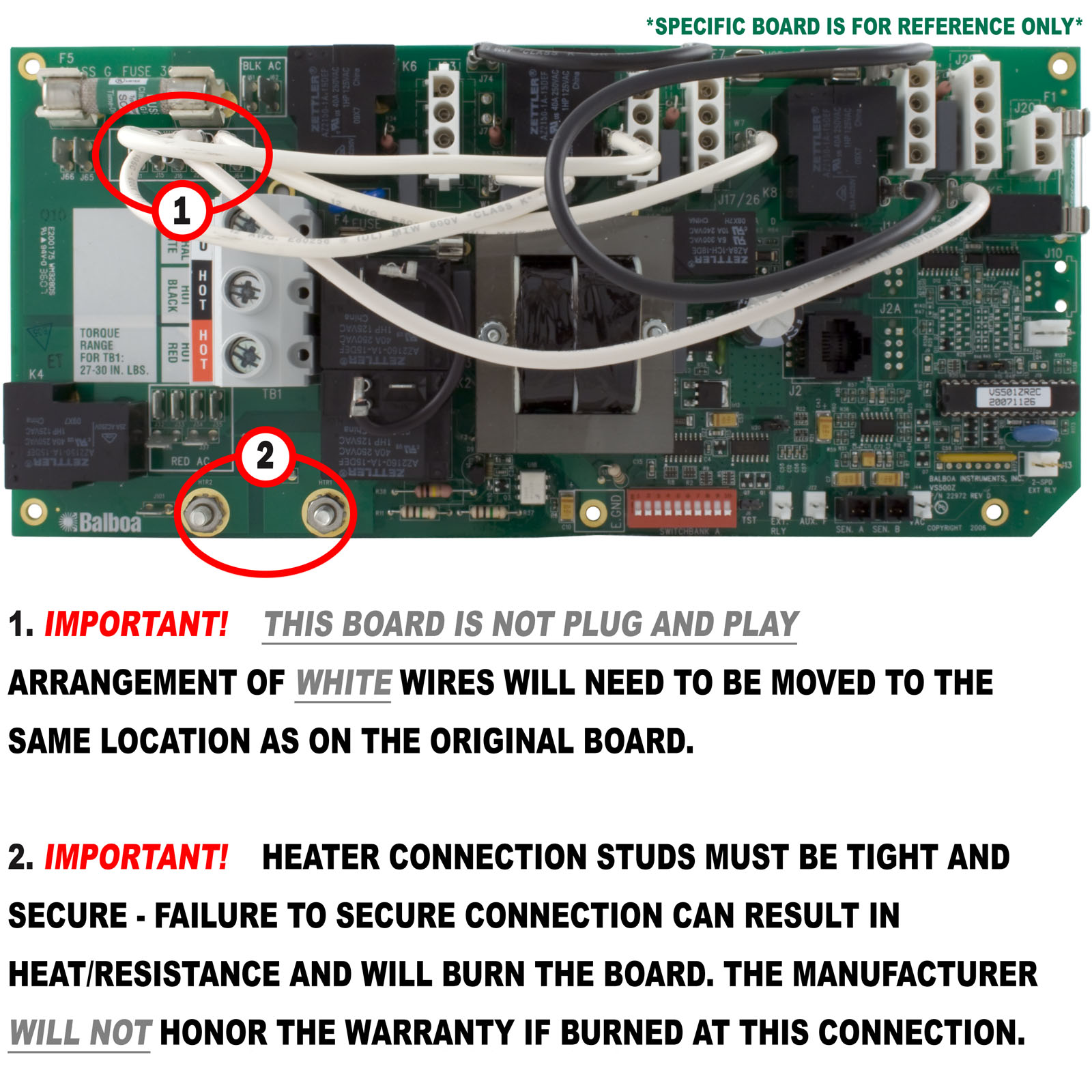
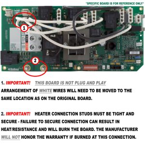
- Older heater strap connection. This board uses the traditional copper strap heater connection (not Plug’n’click). A Plug’n’click upgrade is available — see the Installation section for details.
- Circuit boards are non-returnable. Contact Parts4Tubs to verify chip number and compatibility before ordering.
📋 Product Overview
The Balboa VS501SZ circuit board (Part Number 54378-03, Chip VS501SZRD2) is a genuine Balboa Water Group PCB for the VS501SZ Serial Standard spa control system. Built on the VS500Z PCB platform (22972 Rev C or D), this board is one of the few VS-series circuit boards engineered to operate at either 120VAC or 240VAC — making it suitable for both 120V portable spas and standard 240V hardwired installations.
The VS501SZ controls a single 2-speed primary pump, an optional blower, ozone, 12V spa lighting, AV/stereo output, and a 5.5kW heater (at 240V; approximately 1.4kW at 120V). An optional off-board second pump can be enabled via DIP A3, and an optional J17/26 output (for blower or Pump 3) can be activated via DIP A7. The board connects to Balboa VL600S and VL701S Serial Standard topside panels.
This board has been used across a range of spa brands including Balboa, Keys, Leisure Bay, Great Lakes, and GPM.
💡 Key Features
✅ Dual-Voltage Operation — configurable for 120VAC or 240VAC / 60Hz; no other VS-series boards in this line offer this flexibility
✅ Two-Speed Pump 1 Control — 240V (or 120V) main jet pump, high and low speed
✅ Optional Blower Output — via on-board connector
✅ Optional Off-Board Pump 2 — enabled via DIP A3
✅ Optional J17/26 Output — blower or additional pump via DIP A7
✅ Circulation Pump Output — 120V optional, J47; shares voltage with ozone via W2
✅ Ozone Generator Output — 120V or 240V field-selectable via W2
✅ Spa Light Output — 12V at J20
✅ AV / Stereo Output — 120V, always-hot
✅ 5.5kW Heater at 240V — approximately 1.4kW at 120V
✅ Persistent Memory (J43) — stores filter settings, set temperature, and heat mode
✅ Dolphin Remote Compatible — Full-Feature and Spa-Only (J1 or J2)
✅ VX20 and VX40S Aux Panel Support — 2-button and 4-button auxiliary panels
✅ M7 Technology — no pressure switch or external sensors required
✅ 1-Year Manufacturer Warranty
✅ Made in the USA — Balboa Instruments, Inc.
🔩 Technical Specifications
| Specification | Value |
|---|---|
| OEM Part Number | 54378-03 |
| Previous Revisions | 54378-01, 54378-02 |
| Chip Number (current) | VS501SZRD2 |
| Chip Numbers Also Replaced | VS501SZR1A, VS501ZR1B, VS501ZR2B, VS240RR2A, VS240RR2B, VS240RR2C, INFI07R1A, VZ501SZ2A, VZ501SZ2B, VZ501Z2A, VZ501Z2B, GVS500SZ |
| PCB Part Number | VS500Z PN 22972 Rev C or D |
| System PN | 54377-03 |
| System Model | VSP-VS501SZ-ACAH |
| Software Version | 51 |
| EPN | 3609 |
| SSID | 100 — 65 — 51 |
| Input Voltage | 120VAC or 240VAC / 60Hz (dual-voltage) |
| Service — 120V configuration | 16A, GFCI-protected, 20A max breaker, 3-wire (hot, neutral, ground) |
| Service — 240V configuration | 40A, GFCI-protected, 50A max breaker, 4-wire (hot, hot, neutral, ground) |
| Heater Output @ 240V | 5.5kW |
| Heater Output @ 120V | Approximately 1.4kW |
| Pump 1 Output | 2-Speed (120V or 240V per supply) |
| Blower Output | 1-Speed (on-board connector) |
| Off-Board Pump 2 | Optional — DIP A3 ON required |
| J17/26 Output | Optional — DIP A7 ON (Blower or 1-speed Pump 3) |
| Circ Pump Output | 120V optional, J47 — must match ozone W2 voltage |
| Ozone Output | 120V or 240V at J29 via W2 |
| Spa Light Output | 12V at J20 |
| AV / Stereo Output | 120V, always-hot |
| DIP Switches | Single Switchbank A: 8 active positions (A1–A10 select) |
| Fuse (logic) | 0.3A 250V |
| Fuse (F7) | 20A 250V — DO NOT REMOVE |
| Fuse | 3A 250V |
| Fuse (F5) | CLASS G 30A |
| TB1 Torque | 27–30 in. lbs. |
| Wire Type | Copper conductors only |
| Heater Connection | Traditional copper strap (10ga jumper strap); Plug’n’click upgrade available |
| Warranty | 1 year (manufacturer) |
⚠️ At 120V: Pump 1, Blower, and other 240V-rated outputs will operate at reduced wattage proportional to supply voltage. The heater is approximately 1.4kW at 120V input.
⚠️ J12 — DO NOT MOVE. Factory set to Pins 1–2 for VS51x/VS5xxS/VS5xxD software. Moving this jumper prevents the board from functioning correctly.
🔄 Compatibility Guide
⚠️ CRITICAL CHIP WARNING — Read carefully:
| Chip | Looks Like | Horizon SKU | Product |
|---|---|---|---|
| INFI07R* | I-N-F-I-0-7-R | 59-138-1682 | VS501SZ 54378-03 — THIS BOARD |
| INF107R* | I-N-F-1-0-7-R | 59-138-1683 | Different VS501 variant |
The 4th character in the chip number is either the letter “I” or the number “1” — look closely at your board’s chip label. These two chips are for different products and are not interchangeable.
Compatible Topside Panels:
| Panel PN | Panel Name | Notes |
|---|---|---|
| 54547-01 | VL600S | PDF-confirmed base panel; connects to J1 only (backlit panels must use J1 only) |
| 51057-01 | VL701S (Serial Standard) | PDF-confirmed base panel |
| 54548, 54681 | VL600S variants | |
| 54617 | VL700S | |
| 51247 | VL701S variant |
ℹ️ VL600S panel note: The VL600S with backlight bulbs installed must connect to J1 only. It is NOT compatible with fully-equipped VS510SZ, VS503/504/514SZ, or VS520SZ systems — but IS compatible with the VS501SZ.
Aux Panel Support:
| Aux Panel | Description |
|---|---|
| VX20 | 2-button aux panel — PDF-confirmed |
| VX40S | 4-button aux panel — PDF-confirmed |
⚠️ A3 + A7 Warning: The panel button layout is not compatible when both A3 and A7 are ON at the same time.
Replaces / Cross-Reference Part Numbers:
| Part Number | Description |
|---|---|
| 54378-03 | This board (current revision) |
| 54378-01, 54378-02 | Earlier revisions |
| 54377-03 | System PN for this PCBA |
| 9710-115 | OEM catalog number |
| 52368 / 53268 | Earlier VS501 board |
| 54357-01, 54357-03 | Related VS501 variants |
| 55036 | Related variant |
| 55197 | GVS500SZ board (gas VS500 variant) |
| 55944 | FV501SZ system |
| 55945 | FV501SZ board |
| 3-60-0092 | OEM catalog number |
| KEYS100 | Keys brand chip number / board |
Compatible Spa Brands / OEM References:
| Brand | Evidence | Status |
|---|---|---|
| Balboa | Primary manufacturer | ✅ Primary |
| Keys Spas | Chip KEYS100 / cross-reference | |
| Leisure Bay | ispaparts.com manufacturer list | |
| Great Lakes | ispaparts.com manufacturer list | |
| GPM | ispaparts.com manufacturer list | ⚠️ SINGLE-SOURCE |
🎛️ Board Functions & Controls
Output Configuration (Setup 1 As Manufactured):
| Output | Connector | Voltage | Notes |
|---|---|---|---|
| Pump 1 | J1 / J2 | 240V (2-Speed) | Main jet pump; 120V option if supply is 120V |
| Blower | On-board | 240V (1-Speed) | Built-in output |
| Off-Board Pump 2 | A3 ON | — | Requires DIP A3 ON; separate relay |
| J17/26 Output | J17/26 | — | DIP A7 ON: Blower or 1-speed Pump 3 |
| Circ Pump | J47 | Match W2 | Voltage = ozone W2 setting |
| Ozone | J29 + W2 | 120V or 240V | W2: Red AC = 240V; White AC = 120V |
| Spa Light | J20 | 12V | — |
| AV / Stereo | — | 120V | Always-hot |
| Heater | HTR1/HTR2 | 5.5kW@240V / ~1.4kW@120V | M7 sensors |
⚠️ Ozone and Circ Pump Voltage Warning: W2 sets the voltage for both J29 (ozone) and J47 (circ pump). They must always use the same voltage. Connecting mismatched devices will damage equipment.
DIP Switchbank A (PDF-CONFIRMED — Base Model VS500SZ/VS501SZ/VS510SZ):
| Switch | OFF Position | ON Position |
|---|---|---|
| A1 | Test Mode OFF (normal) | Test Mode ON — technician only |
| A2 + A10 | See Table 1 — amp draw control | See Table 1 |
| A3 | Off-board Pump 2: Disabled | Off-board Pump 2: Enabled |
| A4 | Aux Freeze — must remain OFF | must remain OFF |
| A5 + A9 | See Circ Mode Table | See Circ Mode Table |
| A6 | 60Hz (US normal) | 50Hz |
| A7 | J17/26 Disabled | J17/26 Enabled (Blower or 1-speed Pump 3) |
| A8 | Fahrenheit | Celsius |
⚠️ Both A3 and A7 ON simultaneously: Panel button layout becomes incompatible — avoid this combination unless using a compatible aux panel.
Table 1 — Heater Amp Draw (A2 + A10):
| A2 | A10 | Max HS Pumps/Blower Before Heater Disables |
|---|---|---|
| OFF | OFF | 0 |
| ON | OFF | 1 |
| OFF | ON | 2 |
| ON | ON | 3 |
Circ Mode Table (A5 + A9):
| A5 | A9 | Circ Mode | Pump 1 Speed |
|---|---|---|---|
| OFF | OFF | Non-circ | 2-Speed |
| ON | OFF | Circ acts like P1 Low (filters/polls) | 1-Speed |
| OFF | ON | 24 Hr with 3°F shut-off | 1-Speed |
| ON | ON | 24 Hr with 3°F shut-off | 2-Speed |
Panel Button Assignments:
| DIP State | Button 5 | Button 6 | Button 7 |
|---|---|---|---|
| A3 OFF, A7 OFF | Pump 1 | Unused | Unused |
| A3 ON, A7 OFF | Pump 1 | Pump 2 | Unused |
| A3 OFF, A7 ON | Pump 1 | J17/26 | Unused |
| A3 ON, A7 ON | Pump 1 | Pump 2 | J17/26 ⚠️ layout incompatible with some panels |
Key Jumpers:
| Jumper | Function |
|---|---|
| J12 | Factory set — DO NOT MOVE. Pins 1–2 for VS51x/VS5xxS/VS5xxD software |
| J43 | Persistent Memory: 2 pins = RESET; 1 pin = Enabled |
| W2 | Ozone/Circ voltage: Red AC = 240V; White AC = 120V |
🔧 Installation Requirements
⚠️ Installation must be performed by a licensed electrician in compliance with NEC and all applicable local codes.
Pre-Installation Checklist:
- [ ] Confirm chip number character by character — look for INFI07R (letter I) vs INF107R (number 1)
- [ ] Confirm supply voltage (120V or 240V) and match to board configuration
- [ ] Record all DIP switch settings before removal
- [ ] Record W2 ozone voltage — confirm it matches circ pump voltage
- [ ] Disconnect all power at the GFCI breaker or disconnect
- [ ] Photograph all wiring and connections
- [ ] Allow capacitors to discharge — 5 minutes after power-off
- [ ] Confirm enclosure is plastic — not for metal enclosures
- [ ] Check heater connection: this board uses copper strap; inspect strap condition before reinstalling
- [ ] Do NOT move J12 jumper
Electrical Requirements — 120V Configuration:
| Requirement | 120V Specification |
|---|---|
| Supply Voltage | 120VAC / 60Hz |
| Service | 16A, GFCI-protected, 3-wire (hot, neutral, ground) |
| Circuit Breaker | 20A maximum |
| GFCI Protection | Class A GFCI — NEC Article 680 |
Electrical Requirements — 240V Configuration:
| Requirement | 240V Specification |
|---|---|
| Supply Voltage | 240VAC / 60Hz |
| Service | 40A, GFCI-protected, 4-wire (hot, hot, neutral, ground) |
| Circuit Breaker | 50A maximum |
| GFCI Protection | Class A GFCI — NEC Article 680 |
Both configurations require: equipment grounding, bonding (NEC Article 680), dedicated circuit, disconnect box within line of sight at least 5 ft from spa, copper conductors only, TB1 torque 27–30 in.lbs.
Heater Connection Note: This board uses the older copper strap (screw-terminal) heater connection, not Plug’n’click. A Plug’n’click upgrade is available using adapters PN 25696 (59-138-1155, Female Molex 6″) and PN 25263 (60-138-1040, Male 16″), which eliminates the copper strap arcing risk entirely. If retaining the copper strap, replace the strap if worn, use a 10ga jumper strap (such as 60-355-1054), and torque to specification.
⚠️ DO NOT REMOVE Fuse F7 (20A 250V) — the PDF specifically warns not to remove this fuse.
Persistent Memory Reset (REQUIRED after any DIP switch change — except A1):
- Power down the spa (disconnect from power source)
- Place jumper across J43 covering both pins
- Power up the spa
- Wait until “GC” is displayed on the panel
- Power down again
- Remove jumper from J43 (or move to cover 1 pin only)
- Power up again
🛡️ Safety Warnings
- ⚠️ ALWAYS disconnect all power before board work — shock hazard
- ⚠️ Licensed electrician installation required; NEC Article 680 compliance mandatory
- ⚠️ Class A GFCI required per NEC Article 680
- ⚠️ Equipment grounding and bonding required per NEC Article 680
- ⚠️ 120V or 240V — verify supply voltage before installing; do not assume voltage
- ⚠️ 50A max breaker at 240V; 20A max at 120V — do not exceed these ratings
- ⚠️ Ozone and Circ Pump must share W2 voltage — mismatch damages equipment
- ⚠️ DO NOT MOVE J12 jumper — factory-set; moving it disables the board
- ⚠️ DO NOT REMOVE Fuse F7 (20A 250V) — per PDF warning
- ⚠️ Do not enable both A3 and A7 simultaneously unless using compatible aux panel layout
- ⚠️ Reset Persistent Memory (J43) after any DIP change (except A1) or new settings will not activate
- ⚠️ INFI07R* vs INF107R* — confirm each character before ordering; these chips are different products
- ⚠️ Circuit boards are non-returnable and special-order — verify before ordering
🔍 Error Codes & Diagnostics
Power-Up Display Sequence:
| Display | Meaning |
|---|---|
| SSID sequence (100 — 65 — 51) | Software Version 51 shown on third display |
| “GC” | Heater 3–6kW range — normal for 240V operation |
| “CG” | Heater 1–3kW range — normal for 120V operation |
| Priming mode | Normal startup |
Common VS-Series Error Messages:
| Display | Meaning | Action |
|---|---|---|
| OH | Overheat | Allow to cool; check hi-limit sensor |
| FLO / FL | Flow error | Check pump, filter, sensors |
| SN / SnA / SnB | Sensor failure | Check Sensor A/B connections |
| PS | Pressure switch fault | Check VAC connector |
| – – – | Frozen sensor or heater fault | Inspect sensors and heater |
🎯 Ideal Applications
| Application | Suitability | Notes |
|---|---|---|
| ♨️ VS501SZ system spas — 240V (chip INFI07R*) | ✅ Direct replacement | Confirm chip — letter I, not number 1 |
| ♨️ VS501SZ system spas — 120V (portable/plug-in) | ✅ Compatible | Same board — verify voltage supply |
| ♨️ Keys Spas (chip KEYS100) | ✅ Confirmed | OEM cross-reference verified |
| ♨️ Leisure Bay spas | ✅ Confirmed | OEM cross-reference verified |
| ♨️ Great Lakes spas | ✅ Confirmed | OEM cross-reference verified |
| ♨️ VL600S / VL701S topside spas | ✅ Compatible | PDF-confirmed panels |
| ♨️ Spas needing both 120V and 240V flexibility | ✅ Unique advantage | Dual-voltage design |
This board is NOT suitable for:
- Chip INF107R* (number 1) — that is a different product
- Fully-equipped VS510SZ or VS520SZ systems (different software/chip)
- Metal enclosure installations
❓ Frequently Asked Questions
Q: How do I tell INFI07R from INF107R on my board? A: Look closely at the 4th character of the chip code on the white label. Position 4 is either the letter “I” (straight vertical stroke with serifs/no serifs depending on font) or the number “1” (usually with a serif or angled top stroke). When in doubt, photograph the label and send it to Parts4Tubs — we will confirm which board you have.
Q: My spa is a portable plug-in 120V — will this work? A: Yes. The VS501SZ is one of the few VS-series boards supporting both 120V and 240V. At 120V, the heater outputs approximately 1.4kW and all other outputs operate proportionally. Confirm your spa’s voltage with the system label inside the equipment box.
Q: Why does the 240V configuration allow up to a 50A breaker instead of 60A? A: The VS501SZ is rated for 40A service at 240V, with a 50A maximum breaker. This is lower than the EL-series and some other VS boards. Do not upsize to a 60A breaker.
Q: Can I upgrade to Plug’n’click heater connection? A: Yes. Use adapter PN 25263 (60-138-1040, Male 16″) on the heater side and PN 25696 (59-138-1155, Female Molex 6″) on the board side to convert to Plug’n’click. The copper strap must then be removed. This upgrade eliminates the arcing risk associated with older copper strap connections.
Q: Can I use both the off-board pump (A3) and J17/26 (A7) at the same time? A: Electrically yes, but the panel button layout becomes incompatible when both A3 and A7 are ON simultaneously. Use this combination only with a compatible aux panel configuration.
Q: Is this board still available? A: This is a special-order item with an estimated 2–5 business day lead time. Contact Parts4Tubs to confirm current availability before ordering.
Q: What is the current replacement for this board? A: The VS510SZ is the currently manufactured replacement in this product line. Contact Parts4Tubs for guidance on which board best fits your specific spa.
Q: What warranty is included? A: 1-year manufacturer warranty. Contact Parts4Tubs for full terms.
📑 Downloads & Resources
📄 Balboa VS501SZ Tech Sheet 54377-03 — Official PDF — Full wiring diagram, DIP switch definitions, connector layout, panel configurations, ozone/circ pump voltage warning
⭐ Why Choose the Balboa VS501SZ (54378-03)
✅ Dual-voltage design — the only VS-series board in this class that runs 120V and 240V
✅ Genuine Balboa Water Group OEM board — VS501SZRD2 chip, original performance
✅ Multiple pump configurations — single pump, optional second pump, optional J17/26 output
✅ AV/Stereo supported — 120V always-hot output
✅ Keys, Leisure Bay, Great Lakes compatibility confirmed — broad legacy spa brand coverage
✅ 1-year manufacturer warranty — Balboa Water Group coverage
✅ Non-returnable — Parts4Tubs verifies chip (INFI07R vs INF107R) before you order
🤝 Why Buy from Parts4Tubs
✅ Fast US shipping
✅ Expert technical advice from spa specialists
✅ Competitive pricing
✅ Full warranty support
✅ Compatible VL600S/VL701S panels, sensors, and heater adapter cables available
✅ Chip number verification before ordering — including INFI07R vs INF107R disambiguation
🔌 Summary
The Balboa VS501SZ circuit board (54378-03, Chip VS501SZRD2) is a dual-voltage OEM PCB for VS501SZ Serial Standard spa control systems — uniquely configurable for either 120VAC or 240VAC service. At 240V it delivers 5.5kW heating; at 120V approximately 1.4kW. It controls a 2-speed Pump 1, optional blower, optional off-board Pump 2 (DIP A3), J17/26 output (DIP A7), ozone, spa light, and AV/stereo. Two critical safety notes: the ozone and circ pump connectors share W2 voltage and must always match; and the J12 jumper must never be moved. This is a special-order, non-returnable board — always verify the chip number character by character (INFI07R with letter “I”, not INF107R with number “1”), confirm your supply voltage, and reset Persistent Memory (J43) after any DIP switch change.
Finding and identifying a replacement Hot Tub Circuit Board (PCB)
If you are looking to replace a failed PCB on your Hot Tub’s spa pack, then quite often identifying the part that you need can be the hardest thing.
Firstly, you are looking for a model number on the actual circuit board itself. Having the model or serial of your hot tub is not going to help at this point, you need to find the number on the PCB itself.
Now, with certain brands of PCB, the number of the replacement PCB that you need is not going to match identically the one you are replacing. Why is that I hear you ask?
Well, normally, it is an updated version. This means that it might have updated firmware on the PCB or be a later revision. Normally, this means that the part number would be slightly different. This is usually indicated with a “12345678 -x” at the end of that part number where x indicated a firmware revision.
In some cases, there will be some following letters on the part number of the circuit board, “12345678 -x MAS” this can indicate that the PCB was used for an OEM meaning it was produced for a certain hot tub manufacturer and the letters identify the manufacturer.
This means if you source an original PCB, it will not have the letters, but will in most cases work just fine.
It can be confusing I know!
What if you can’t find a model number?
If you can’t find a model number on the PCB itself, then you need to look for a model number on the spa pack. Normally, there is a sticker on the outside of the spa pack that tells you the current ratings and input voltages etc and this will have a model number.
In general, most spa packs in the USA are manufactured by Balboa, Hydro-Quip, ACC or Gecko. I know I am generalising here, but if you have a spa pack that has the brand of your hot tub on, it will be an OEM so the key is identifying who made the original box.
From there, you can normally find an original PCB that you will be able to switch out.
For example, the Balboa VS (value series) is a very popular spa pack that has been used by multiple hot tub manufacturers under their own brand names. Whatever they have called it, strip it back and it is still a Balboa VS.
Visual Inspection
One of the most important things you can do when you are looking for a replacement is to visually inspect the PCB that you have versus the picture online of the replacement you are considering. They need to look the same even if there are the differences in firmware revisions or OEM part numbers, you should be visually replacing a PCB that looks like the one you have.
Configuring a replacement Hot Tub Circuit Board (PCB)
When you get a new PCB, you are more than likely going to need to configure it. Most PCBs have a number of different modes and setups that the can operate in. For this, you will need to manual or spec sheet to guide you.
For things like DIP switches, most of the time you can copy the settings from your original circuit board. You are looking for things like setting the voltage as a lot of PCBs can be configured to run on both 115V and 230V.
You may need to move jumpers or even wires to configure voltages – the key here is that you read the schematic and don’t expect the PCB to just work out of the box – it usually doesn’t.
Troubleshooting a Hot Tub Circuit Board (PCB)
Here are some common things you will see when you replace a PCB on a hot tub.
You press the buttons on the topside control and they don’t control the right parts (pumps or blower etc) – this is a mode configuration thing and you will either need to change some DIP switches on the PCB or an internal or low level programming mode on the topside control. Check the manual for how to do this.
You turn on the hot tub and it trips the breaker – it is not common for a new PCB to fail out of the box (I have not seen one yet!) However, a common mistake is that the voltage has not been set correctly. If it is set for 115V and then you try and turn it on, the current draw will be a lot more (twice) than expected and the breaker will trip.
To check this, unplug all of your kit – heater, pumps, blower and then turn on the PCB. If it trips with nothing plugged in, usually the voltage is incorrectly set and what is happening is that live current is being sent to the ground – because you have 4 wires into the PCB rather than 3. Current on the ground loop causes the trip. Check the settings to make sure it is configures for 230V.
It might not trip until you physically turn on a pump or a blower. As mentioned, if the pack is set to 115V and your pump is meant for 230V, it will draw twice the current at half the voltage and trip your breaker. Check the manual for info on how to set the voltage.
| Circuit Board Application | Balboa Water Group |
|---|---|
| Circuit Board Model | VS501SZ |
| Circuit Board Type | New |
| Manufacturers Part Number | 54378-01 |
| H Part# | 59-138-1682 |
Related products
Balboa Topside Controls (Overlays)
$334.68
Out of stock
Gecko Heating
$112.64
Out of stock
Hydro-Quip Overlays
$123.49
Waterway Topside Controls
$232.19
Sundance Topside Controls
$330.25
Sundance Circuit Boards
⚙️ Sundance® / Jacuzzi® 6600-390 880 NT System Spa Circuit Board (2-Pump with PermaClear®)
$966.39
Gecko Spa Pack Controls
$343.01
Sundance Topside Controls
$319.99