

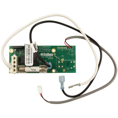
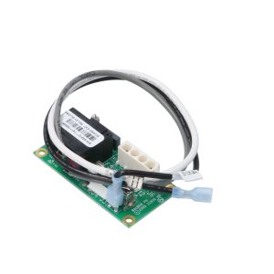
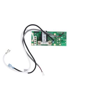
Balboa X-P231 Daughter Board (G1910) — 1-Speed High Amp Expander PCB
$91.41
🛠️ Balboa X-P231 Daughter Board (G1910) — 1-Speed High Amp Expander PCB
Add branch circuit protection and high-amperage pump expansion to your VS/EL-series spa control system
📋 Product Overview
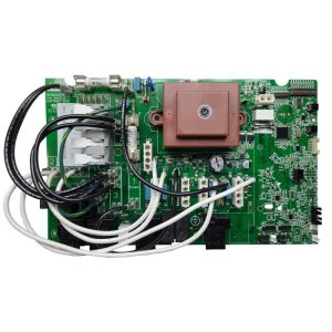
The Balboa X-P231 Daughter Board (G1910) is a genuine Balboa Water Group expander / daughter circuit board designed to add a fused, high-amperage 1-speed pump output to compatible Balboa VS- and EL-series spa control systems. It connects directly to the main spa PCB and delivers its own independent 30A branch circuit protection — preventing high-current pump loads from over-burdening fuse F5 on the main board.
Primarily used in Balboa VS514SZ and GS501SZ spa control systems, the X-P231 is also the correct expander board for VS513Z, VS515Z, and EL2001 systems where a 1-speed third pump or secondary high-amperage device is required. In EL2001 systems, installing this board enables simultaneous operation of two 2-speed pumps plus a blower — a configuration that would otherwise exceed the main PCB fuse rating without dedicated branch protection.
This is the replacement for the older X-P style daughter board in systems that have been upgraded or are handling equipment that demands greater current capacity. It ships complete with all necessary cables and new mounting hardware, making it a clean, self-contained upgrade or service replacement.
✅ Key Features
✅ Genuine Balboa Water Group Component — OEM expander board (G1910 / 53681) designed and manufactured by Balboa for the VS/EL control system platform
✅ High-Amp Branch Circuit Protection — Built-in 30A fuse delivers dedicated branch circuit protection for the pump output, preventing overload on the main PCB fuse F5
✅ 1-Speed Pump Output — Controls a single-speed pump at full system voltage; suitable for third pumps, high-amperage secondary pumps, and other 1-speed accessories
✅ Compatible with VS514SZ and GS501SZ Systems — Direct-fit expander board for these control systems; also supports VS513Z, VS515Z, and EL2001 platforms
✅ EL2001 Multi-Device Support — Enables the EL2001 system to simultaneously run two 2-speed pumps plus a blower — a configuration that requires this board for safe operation
✅ Replaces Older X-P Daughter Board — Drop-in upgrade for VS-series systems running the standard X-P expander where higher amperage capacity is needed
✅ Complete Kit — Ready to Install — Includes all attached cables and new mounting hardware; no additional wiring harness required
✅ 1-Year Manufacturer Warranty — Backed by Balboa Water Group’s standard 1-year limited warranty
🔩 Technical Specifications
| Specification | Value |
|---|---|
| Manufacturer Part Number | G1910 |
| Board Model | X-P231 |
| Board Type | Daughter Board / Expander Board |
| Board Function | 1-Speed Pump Output with Branch Circuit Protection |
| Fuse Rating | 30A (protects pump output; protects main PCB fuse F5) |
| Number of Relays | 1 (1-speed pump relay) |
| Compatible System Voltage | 240VAC / 60Hz (North American UL systems) |
| Board Dimensions | Approx. 3⅛ × 1⅝ in. (single source — verify before ordering) |
| Included Hardware | Attached cables + new mounting hardware |
| Warranty | 1 Year (Balboa Water Group) |
| Certifications | Please refer to manufacturer documentation or contact Parts4Tubs |
| Operating Temperature Range | Please refer to manufacturer documentation or contact Parts4Tubs |
⚠️ Important: This is an expander / daughter board — it is NOT a standalone main circuit board. It must be installed into a compatible Balboa VS/EL control system. Always disconnect all power before installation.
ℹ️ US Voltage Note: The X-P231 G1910 is the North American UL version designed for 240VAC / 60Hz systems. A separate CE version (PN 55025) exists for European 230VAC / 50Hz systems — do not interchange them.
🔄 Compatibility Guide
Primary Compatible Control Systems
| System | Notes |
|---|---|
| Balboa VS514SZ | Primary — X-P231 is a factory component of this system |
| Balboa GS501SZ | Primary — X-P231 is a factory component of this system |
| Balboa VS513Z | Compatible replacement |
| Balboa VS515Z | Compatible replacement |
| Balboa EL2001 | Use when running 2 × 2-speed pumps + 1 blower simultaneously |
| Balboa VS510SZ / VS510DZ | Secondary expander board found in these systems |
Replaces Part Numbers
| Part Number | Description |
|---|---|
| G1910 | Balboa Water Group (manufacturer, current) |
| 53681 | Balboa Water Group (OEM alternate number) |
| 33-53681-K | Kit variation |
| 59-138-1800 | Alternate replacement reference |
⚠️ Always verify compatibility by the part number label on your existing daughter/expander board — not by appearance. Many Balboa expander boards look similar but control different pump speeds and amperage ratings. The X-P231 G1910 is specifically for 1-speed, high-amp applications. For 2-speed pump expansion, see related boards (G1960, G1920). For blower expansion, see the X-B expander (53310).
💡 Board Function & Operation
What This Board Does
The X-P231 daughter board connects to the main spa PCB via the expander board connector and provides:
| Function | Detail |
|---|---|
| Pump Output | Switches one 1-speed pump at full line voltage |
| Branch Circuit Protection | 30A fuse isolates pump current from main PCB F5 |
| Activation | Controlled via DIP switch A3 on the main board (must be set to ON to enable) |
| Mounting | Clips or mounts inside the existing control system enclosure |
When Is This Board Required?
| Situation | X-P231 Needed? |
|---|---|
| Adding a 1-speed third pump to a VS/EL system | ✅ Yes |
| Replacing older X-P board where higher amperage is needed | ✅ Yes |
| Running EL2001 with 2 × 2-speed pumps + blower | ✅ Yes |
| Running a 2-speed pump 2 expansion | ❌ No — use G1960 or G1920 instead |
| Adding a blower expansion output | ❌ No — use X-B expander (53310) instead |
DIP Switch Setting Required
When installing this board on a VS-series system, DIP Switch A3 must be set to ON on the main circuit board to enable the expander pump output. Setting A3 to OFF disables the off-board pump, regardless of whether the daughter board is physically connected.
⚠️ Always power down completely and reset Persistent Memory (J43) after changing any DIP switch setting, or the new settings will not take effect.
⚙️ Installation Requirements
⚠️ IMPORTANT: All electrical work must be performed by a licensed electrician in compliance with the National Electrical Code (NEC) Article 680 and all applicable local codes.
Pre-Installation Checklist
- [ ] Confirm the existing expander board part number matches X-P231 / G1910 / 53681
- [ ] Verify the parent control system is a compatible VS/EL series model
- [ ] Disconnect ALL power at the circuit breaker and GFCI before beginning
- [ ] Photograph existing wiring and daughter board mounting position
- [ ] Allow capacitors to discharge — wait at least 5 minutes after power-off
- [ ] Note existing DIP switch positions on the main board before changing
Electrical Requirements (Parent Control System)
| Requirement | Specification |
|---|---|
| Parent System Voltage | 240VAC / 60Hz |
| GFCI Protection | Class A GFCI required per NEC Article 680-42 |
| Ground Connection | Equipment grounding and bonding required per NEC Article 680 |
| Dedicated Circuit | Required |
| Disconnect | Within line of sight of spa, at least 5 ft from water (NEC) |
| Wire | Copper conductors only |
Installation Steps (General)
- Disconnect all power at the main breaker and GFCI — verify with a voltage tester
- Open the control system enclosure
- Remove the old X-P or X-P daughter board if present
- Mount the X-P231 board in the enclosure using the included hardware
- Connect the attached cables to the main PCB expander connector
- Connect the pump cord to the X-P231 output
- Set DIP Switch A3 to the ON position on the main PCB
- Reset Persistent Memory via J43 jumper (per system instructions)
- Close enclosure and restore power
- Enter Priming Mode and verify pump operation via the topside panel
💡 Tip: Record the DIP switch setup and new board part number on the label inside the control system lid — this is essential for any future service call.
🔒 Safety Warnings
Electrical Safety:
- ⚠️ ALWAYS disconnect ALL power at the breaker and GFCI before touching any wiring or components
- ⚠️ Installation MUST be performed by a licensed electrician only
- ⚠️ This board is designed for 240VAC / 60Hz North American systems — do not install in CE systems
- ⚠️ Class A GFCI protection is mandatory per NEC Article 680-42
- ⚠️ Use copper conductors ONLY — no aluminum wiring
- ⚠️ All wiring must comply with NEC Article 680 and applicable local electrical codes
Board-Specific Warnings:
- ⚠️ Do NOT use this board for 2-speed pump expansion — it controls 1-speed pumps only
- ⚠️ Do NOT substitute fuse ratings — use only the correct 30A replacement fuse (Balboa part #30136 or equivalent)
- ⚠️ Setting DIP switches incorrectly will cause abnormal system behavior or component damage
- ⚠️ Always reset Persistent Memory (J43) after DIP switch changes — failure to do so will cause improper operation
- ⚠️ Ensure the 30A fuse is properly seated before restoring power
Post-Installation:
- ⚠️ Verify pump responds correctly via the topside control panel
- ⚠️ Check for any error codes on initial startup
- ⚠️ Confirm GFCI protection is functioning correctly before resuming spa use
❓ Frequently Asked Questions
Q: How do I know if this is the right expander board for my spa? A: Locate the part number label on your existing daughter/expander board inside the control system enclosure. If it reads X-P231, 53681, or G1910, this is the correct replacement. Also confirm your control system model — this board is used in VS514SZ, GS501SZ, VS513Z, VS515Z, and EL2001 systems. Contact Parts4Tubs with your system model and existing board label if unsure.
Q: What is the difference between the X-P231 (G1910) and the standard X-P daughter board? A: The X-P231 G1910 is the high-amp version, providing its own 30A fused branch circuit output. The standard X-P board does not include this dedicated fuse protection. The X-P231 is recommended when the pump or device being controlled draws enough current that it would otherwise risk overloading fuse F5 on the main PCB.
Q: What is the difference between G1910 and G1900? A: Both are 1-speed Balboa expander boards for VS/EL-series systems, but they serve different positions. The G1910 (X-P231) is the high-amp version for VS514SZ / GS501SZ and related systems. The G1900 is a separate 1-speed expander for pump number 2 in VS510SZ / VS510DZ systems. Do not interchange them without confirming compatibility by the board part number label.
Q: Can I use this board with the EL2001 main board? A: Yes. When installed on an EL2001 system, the X-P231 G1910 enables the system to simultaneously operate two 2-speed pumps and one blower — a three-device configuration that requires this board to safely distribute the current load.
Q: Does this board require a licensed electrician to install? A: Yes. Any work inside a hot tub electrical control enclosure is covered by NEC Article 680 and requires a licensed electrician in most US jurisdictions. A permit may also be required depending on your local code.
Q: Will I need to change DIP switch settings on my main board? A: Yes. DIP Switch A3 on the main circuit board must be set to ON to enable the expander pump output. After changing DIP switches, you must also reset Persistent Memory via jumper J43, or the new settings will not take effect. Refer to your system’s tech sheet for the exact procedure.
Q: What warranty is included? A: Balboa Water Group provides a 1-year limited warranty against defects in materials and workmanship from the date of purchase. Contact Parts4Tubs for warranty assistance.
Q: Can I order just the fuse separately if it blows? A: Yes. The 30A fuse used on this board is Balboa part #30136. Contact Parts4Tubs for availability.
🏆 Why Choose the Balboa X-P231 G1910?
✅ Genuine OEM Component — Actual Balboa Water Group part, not a generic substitute; ensures correct relay rating and fuse specification for your system
✅ High-Amp Safety — The built-in 30A fuse protects both the daughter board circuit and the main PCB from overcurrent damage caused by high-amperage pump loads
✅ Complete Kit — Ships with all cables and new mounting hardware; no need to source separate connectors or hardware
✅ Broad VS/EL Compatibility — Supports VS514SZ, GS501SZ, VS513Z, VS515Z, and EL2001 systems — one of the most widely used expander boards in the Balboa VS platform
✅ Enables Advanced Configurations — The key component allowing EL2001 systems to support two 2-speed pumps plus a blower simultaneously
✅ Direct Replacement — Replaces 53681 and older X-P boards in one step with no modifications to the enclosure
✅ 1-Year Warranty — Manufacturer-backed warranty provides peace of mind on every installation
🤝 Why Buy From Parts4Tubs?
✅ US-based company with expert local support
✅ Fast US shipping on in-stock parts
✅ Spa specialists available for technical advice and compatibility verification
✅ Competitive pricing on genuine Balboa OEM parts
✅ Full warranty support — we handle claims with the manufacturer on your behalf
✅ Easy returns within 30 days on eligible items
✅ Compatible parts available — main boards, sensors, topsides, heater kits, and more
✅ Help identifying the correct board based on your existing part number and system label
🔌 Summary
The Balboa X-P231 Daughter Board (G1910) is a genuine OEM expander board that adds a dedicated, 30A-fused, 1-speed pump output to compatible Balboa VS514SZ, GS501SZ, VS513Z, VS515Z, and EL2001 spa control systems. It protects your main PCB from high-amperage overload, enables advanced multi-device configurations on the EL2001, and ships complete with cables and mounting hardware for a clean, professional installation. If your existing X-P daughter board has failed, or you need to upgrade from the standard X-P to add proper high-amp branch circuit protection, this is the exact replacement for the job. Order from Parts4Tubs today and get your spa running safely.

Parts4Tubs is proud to be a Balboa Authorized Online Seller - make sure you only buy genuine Balboa parts from trusted sources.
Finding and identifying a replacement Hot Tub Circuit Board (PCB)
If you are looking to replace a failed PCB on your Hot Tub’s spa pack, then quite often identifying the part that you need can be the hardest thing.
Firstly, you are looking for a model number on the actual circuit board itself. Having the model or serial of your hot tub is not going to help at this point, you need to find the number on the PCB itself.
Now, with certain brands of PCB, the number of the replacement PCB that you need is not going to match identically the one you are replacing. Why is that I hear you ask?
Well, normally, it is an updated version. This means that it might have updated firmware on the PCB or be a later revision. Normally, this means that the part number would be slightly different. This is usually indicated with a “12345678 -x” at the end of that part number where x indicated a firmware revision.
In some cases, there will be some following letters on the part number of the circuit board, “12345678 -x MAS” this can indicate that the PCB was used for an OEM meaning it was produced for a certain hot tub manufacturer and the letters identify the manufacturer.
This means if you source an original PCB, it will not have the letters, but will in most cases work just fine.
It can be confusing I know!
What if you can’t find a model number?
If you can’t find a model number on the PCB itself, then you need to look for a model number on the spa pack. Normally, there is a sticker on the outside of the spa pack that tells you the current ratings and input voltages etc and this will have a model number.
In general, most spa packs in the USA are manufactured by Balboa, Hydro-Quip, ACC or Gecko. I know I am generalising here, but if you have a spa pack that has the brand of your hot tub on, it will be an OEM so the key is identifying who made the original box.
From there, you can normally find an original PCB that you will be able to switch out.
For example, the Balboa VS (value series) is a very popular spa pack that has been used by multiple hot tub manufacturers under their own brand names. Whatever they have called it, strip it back and it is still a Balboa VS.
Visual Inspection
One of the most important things you can do when you are looking for a replacement is to visually inspect the PCB that you have versus the picture online of the replacement you are considering. They need to look the same even if there are the differences in firmware revisions or OEM part numbers, you should be visually replacing a PCB that looks like the one you have.
Configuring a replacement Hot Tub Circuit Board (PCB)
When you get a new PCB, you are more than likely going to need to configure it. Most PCBs have a number of different modes and setups that the can operate in. For this, you will need to manual or spec sheet to guide you.
For things like DIP switches, most of the time you can copy the settings from your original circuit board. You are looking for things like setting the voltage as a lot of PCBs can be configured to run on both 115V and 230V.
You may need to move jumpers or even wires to configure voltages – the key here is that you read the schematic and don’t expect the PCB to just work out of the box – it usually doesn’t.
Troubleshooting a Hot Tub Circuit Board (PCB)
Here are some common things you will see when you replace a PCB on a hot tub.
You press the buttons on the topside control and they don’t control the right parts (pumps or blower etc) – this is a mode configuration thing and you will either need to change some DIP switches on the PCB or an internal or low level programming mode on the topside control. Check the manual for how to do this.
You turn on the hot tub and it trips the breaker – it is not common for a new PCB to fail out of the box (I have not seen one yet!) However, a common mistake is that the voltage has not been set correctly. If it is set for 115V and then you try and turn it on, the current draw will be a lot more (twice) than expected and the breaker will trip.
To check this, unplug all of your kit – heater, pumps, blower and then turn on the PCB. If it trips with nothing plugged in, usually the voltage is incorrectly set and what is happening is that live current is being sent to the ground – because you have 4 wires into the PCB rather than 3. Current on the ground loop causes the trip. Check the settings to make sure it is configures for 230V.
It might not trip until you physically turn on a pump or a blower. As mentioned, if the pack is set to 115V and your pump is meant for 230V, it will draw twice the current at half the voltage and trip your breaker. Check the manual for info on how to set the voltage.
Related products

Balboa Circuit Boards
Balboa X-B Blower Expander Board Kit — 53310 (VS / EL2001 Systems)
$41.81
Balboa Circuit Boards
$554.40
Balboa Circuit Boards
$375.00
Balboa Circuit Boards
Coleman / MAAX 100 Series Spa Circuit Board — 101285 (Chip 115/7R1x)
$463.36

Balboa Circuit Boards
$89.17
Out of stock
Balboa Circuit Boards
$633.93
Balboa Circuit Boards
Balboa 1000LE Spa Circuit Board — 52491 (Duplex Digital, Pressure Switch)
$252.58
Balboa Circuit Boards
Balboa D1SR Spa Circuit Board — 51485 (Dimension One Serial Deluxe)
$267.69