

HydroQuip® ECO-2 Replacement Circuit Board — 33-0024-R6 — CS6200 / CS9200 / EP2200 Series
$536.64
Circuit Board, HydroQuip, ECO-2, 4200/6200/9200, JST Cable
2 in stock
Fast dispatch
Order in
--:--:--
for shipping today
⚡ HydroQuip® ECO-2 Replacement Circuit Board — 33-0024-R6 — CS6200 / CS9200 / EP2200 Series
Genuine HydroQuip® ECO-2 replacement PCB for CS6200, CS9200, ES6200, ES9200, CS4200, EasyPak EP2200, and PS6502 Series spa control systems.
⚠️ IMPORTANT — PLEASE READ BEFORE ORDERING
- Confirm your system model before ordering. This board is for HydroQuip ECO-2 Series systems — specifically CS6200, CS9200, ES6200, ES9200, CS4200, EasyPak EP2200, and PS6502 Series. It is not compatible with ECO-2+2 (CS6220/9220), ECO-3 (CS6330/9330), or 240V ECO-2 CE systems.
- This is a 115V/120V board. Horizon lists it as 115V; retailers list it as 120V — both refer to the same US residential voltage standard. This board is NOT compatible with 240V systems. The 240V version of the ECO-2 is a separate board (33-0024CE-K).
- New version — fiber optic lighting no longer supported. The current R6 revision does not support fiber optic lighting. It supports a standard 12V on/off spa light only. If your existing system was configured for fiber optic, you will need to switch to a standard 12V light.
- Temperature and hi-limit sensors are sold separately. This board does not include sensors. Order sensors separately before installation.
- Non-returnable. Circuit boards cannot be resold to another spa owner as new once purchased. Confirm compatibility before ordering. Damage from incorrect installation is also not covered under warranty.
🔌 Product Overview
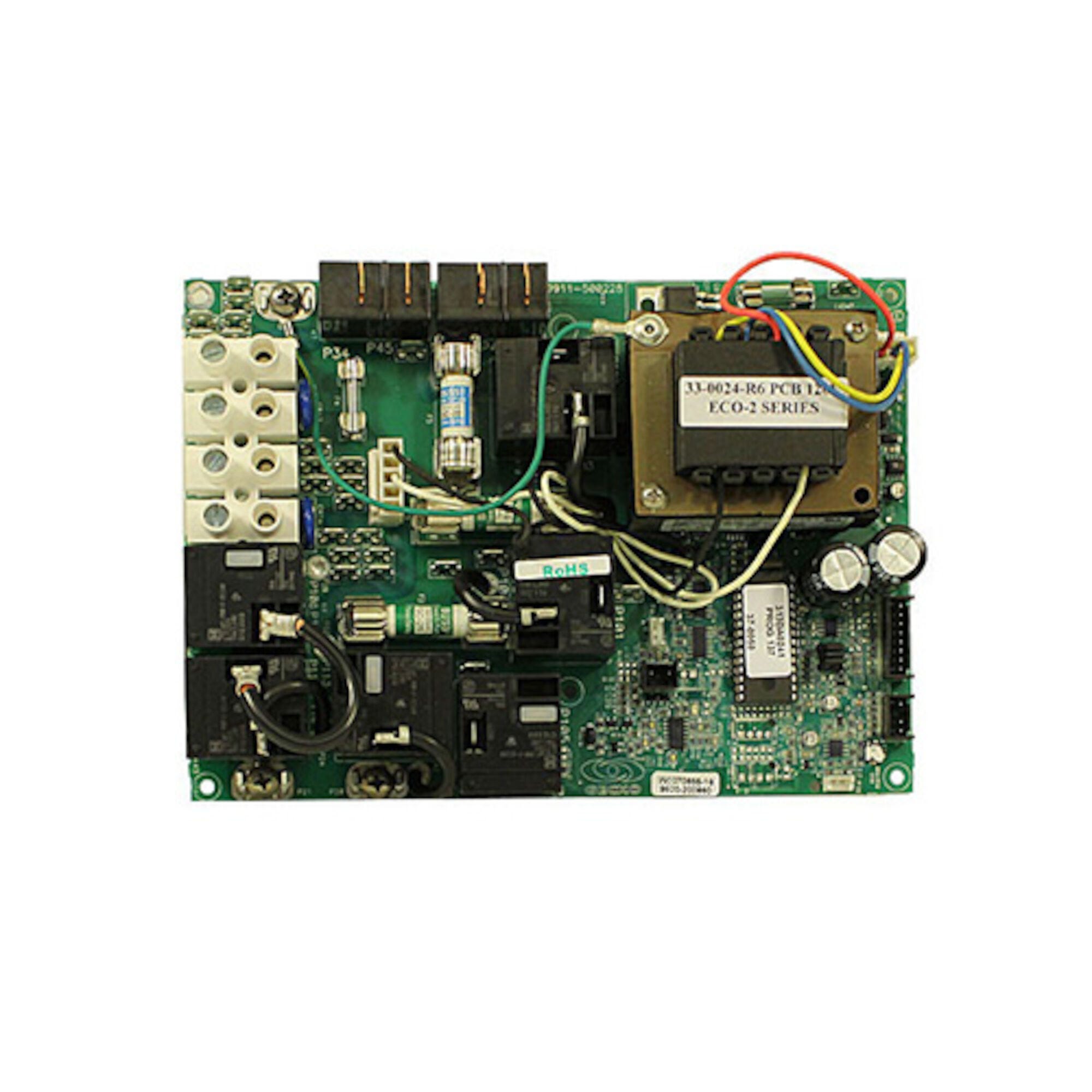
The HydroQuip® ECO-2 circuit board (part number 33-0024-R6) is the current replacement PCB for HydroQuip ECO-2 Series spa control systems including the CS6200, CS9200, ES6200, ES9200, CS4200, EasyPak EP2200, and PS6502 Series. The R6 revision is a factory-new board that replaces all earlier ECO-2 board revisions (R1 through R5) as well as the original 33-0024-K.
The ECO-2 is HydroQuip’s entry-level digital spa control platform designed for 115V/120V hot tub systems. This board uses a JST cable connector system and supports one primary pump, an auxiliary output, and a standard 12V spa light. Temperature and hi-limit sensors are not included and must be ordered separately.
🌟 Key Features
✅ Genuine HydroQuip® OEM replacement PCB — current R6 revision
✅ Part Number: 33-0024-R6 (also listed as HQP330024R6)
✅ Replaces all earlier ECO-2 revisions: 33-0024-K, 33-0024-R1, 33-0024-R2, 33-0024-R3, 33-0024-R4, 33-0024-R5, 9298-20
✅ Board dimensions: 5¾” x 8″
✅ JST cable connector system
✅ 115V/120V operation — standard US residential voltage
✅ Compatible with ECO-2, ECO-6, and ECO-7 spaside topside controls
✅ Standard 12V on/off spa light supported
✅ Factory-new — never installed
✅ 1-year limited manufacturer’s warranty
⚠️ Fiber optic lighting is NOT supported on the R6 revision. This board supports standard 12V on/off lighting only.
⚠️ Temperature and hi-limit sensors sold separately — not included with this board.
🔩 Technical Specifications
| Specification | Value |
|---|---|
| Part Number | 33-0024-R6 (also: HQP330024R6) |
| Board Series | HydroQuip ECO-2 Digital |
| Compatible Systems | EasyPak EP2200; HydroQuip CS4200, CS6200, CS9200; ES6200, ES9200; ECO-2 Series; PS6502 Series |
| Voltage | 115V / 120V (60Hz) |
| Board Dimensions | 5¾” x 8″ |
| Connector Type | JST Cable |
| Spa Light | Standard 12V on/off |
| Fiber Optic | Not supported (R6 revision) |
| Sensors Included | No — temperature and hi-limit sensors sold separately |
| Board Type | New (factory replacement) |
| Warranty | 1-year limited manufacturer’s warranty |
| Returns | Non-returnable |
🔗 Compatibility Guide
Compatible HydroQuip Control Systems:
| System Model | Series |
|---|---|
| CS4200 | ECO-2 Series |
| CS6200 | ECO-2 / 6200 Series |
| CS9200 | ECO-2 / 9200 Series |
| ES6200 | ECO-2 / 6200 Series |
| ES9200 | ECO-2 / 9200 Series |
| EasyPak EP2200 | EP2200 Series |
| PS6502 | PS6502 Series |
⚠️ Not compatible with: CS6220/9220 (ECO-2+2 — requires 33-0024D-K) | CS6330/9330 (ECO-3+2 — requires separate board) | PS6603 | 240V systems (requires 33-0024CE-K)
Replaces These Part Numbers:
| Part Number | Notes |
|---|---|
| 33-0024-K | Original ECO-2 board |
| 33-0024-R1 | Earlier revision |
| 33-0024-R2 | Earlier revision |
| 33-0024-R3 | Earlier revision |
| 33-0024-R4 | Earlier revision |
| 33-0024-R5 | Earlier revision |
| 9298-20 | Cross-reference PN |
Compatible Topside Spaside Controls:
| Part Number | Description |
|---|---|
| 58-355-4102 | ECO-2 Oval Spaside Control, 10′ cord — P1, Aux, Light |
| 58-355-4103 | ECO-2 Oval Spaside Control, 25′ cord — P1, Aux, Light |
| 58-355-4106 | ECO-6 Rectangular Spaside Control, 10′ cord — P1, Aux, Light |
| 58-355-4107 | ECO-6 Rectangular Spaside Control, 25′ cord — P1, Aux, Light |
| 58-355-4120 | ECO-7 Spaside Control, 4-Button, Large Rectangular, 10′ cord — P1, Light |
Recommended Accessories:
| Part Number | Description |
|---|---|
| 59-355-1020 | Temp Sensor, HydroQuip, 10ft, 3/8″ dia, 4-pin — for systems after 5/03 |
| 59-355-1025 | Hi Limit Sensor, HydroQuip, 18″, 1/4″ dia, 2-pin — for systems after 5/03 |
| 60-155-1005 | Surge Protector, Intermatic, 115V/230V |
🛠️ Installation Requirements
⚠️ Installation must be performed by a licensed electrician in compliance with NEC and all applicable local codes.
Pre-Installation Checklist:
- [ ] Confirm system model is CS4200, CS6200, CS9200, ES6200, ES9200, EasyPak EP2200, or PS6502
- [ ] Confirm voltage is 115V/120V — this board is NOT for 240V systems
- [ ] Order temperature and hi-limit sensors separately before beginning (not included)
- [ ] Note: fiber optic lighting is no longer supported — switch to standard 12V light if applicable
- [ ] Disconnect all power at GFCI breaker or service disconnect
- [ ] Photograph all wiring and connector positions before removal
- [ ] Review HydroQuip Eco 2 PCB Revision Explanation document (ECO2PCBREVISIONS.PDF) for any version-specific wiring notes
Electrical Requirements:
| Requirement | Specification |
|---|---|
| Supply Voltage | 115V / 120V / 60Hz |
| GFCI | Class A GFCI required — NEC Article 680 |
| Ground & Bonding | Required — NEC Article 680 |
| Dedicated Circuit | Required |
| Disconnect Box | Within line of sight of spa, at least 5 ft away |
| Wire Type | Copper conductors only |
⚠️ Safety Warnings
- ⚠️ ALWAYS disconnect all power before circuit board work
- ⚠️ Licensed electrician installation required; NEC Article 680 compliance mandatory
- ⚠️ GFCI required; grounding and bonding required per NEC Article 680
- ⚠️ 115V/120V only — do not install in 240V systems
- ⚠️ Fiber optic lighting not supported — do not attempt to connect fiber optic components
- ⚠️ Sensors not included — do not operate without correctly installed temperature and hi-limit sensors
- ⚠️ Damage from incorrect installation is NOT covered under warranty
- ⚠️ Non-returnable — verify compatibility before ordering
🔧 Troubleshooting Guide
| Symptom | Possible Cause | Suggested Action |
|---|---|---|
| No power / no display | Board failure; blown fuse; no power supply | Confirm power supply; check fuses; confirm GFCI is not tripped |
| Heater not activating | Missing or faulty sensors; pressure switch fault | Confirm sensors are installed; check pressure switch connection |
| Temperature readings incorrect | Wrong sensor type; sensor connection issue | Verify sensor PN (59-355-1020 for temp) and wiring |
| Hi-limit fault / OH error | Hi-limit sensor fault; overheating condition | Check hi-limit sensor (59-355-1025); verify water flow |
| Light not working | Fiber optic connected to 12V output (incompatible) | R6 board requires standard 12V light — fiber optic not supported |
| Topside unresponsive | Incompatible topside; cable fault | Confirm topside is ECO-2, ECO-6, or ECO-7 compatible model |
| Board does not power on after install | Incorrect voltage (240V system); reversed connectors | Confirm 115V/120V system; re-check all JST connector orientations |
❓ Frequently Asked Questions
Q: What is the difference between 33-0024-R6 and the original 33-0024-K? A: The 33-0024-R6 is the current replacement for the original 33-0024-K and all intermediate revisions (R1 through R5). The R6 is a redesigned board that addresses issues found in earlier revisions. The most significant change in the new version is that fiber optic lighting is no longer supported — the board supports standard 12V on/off lighting only.
Q: My spa has fiber optic lighting. Can I use this board? A: The R6 revision does not support fiber optic lighting. If your spa used fiber optic lights with an earlier ECO-2 board, you will need to replace the fiber optic system with a standard 12V spa light to use this board.
Q: Are sensors included? A: No. Temperature and hi-limit sensors are sold separately. You will need to order the appropriate HydroQuip sensors before installation. The recommended sensors for systems manufactured after May 2003 are the temperature sensor (59-355-1020) and hi-limit sensor (59-355-1025). Contact Parts4Tubs to confirm the correct sensors for your specific system.
Q: Can this board be used in a 240V spa? A: No. The 33-0024-R6 is a 115V/120V board only. For 240V ECO-2 systems, the correct board is the 33-0024CE-K. Do not install this board in a 240V system.
Q: What topsides are compatible with this board? A: The ECO-2, ECO-6, and ECO-7 spaside controls listed above are confirmed compatible. All feature P1 (pump 1), Aux, and Light button configurations. Contact Parts4Tubs to confirm your existing topside is compatible.
Q: My system is a CS6220 or 9220. Does this board fit? A: No. The CS6220/9220 systems use the ECO-2+2 series, which requires the 33-0024D-K board. The 33-0024-R6 is for CS6200/9200 systems only.
Q: What documentation is available for installation? A: HydroQuip publishes several documents for ECO-2 Series systems, including the ECO-2 PCB Revision Explanation, Solid State Startup Sheet, Circulation Pump Installation Guide, ECO-2/6 Series Incoming Wiring Diagram, and 6200 Series Troubleshooting guide. Contact Parts4Tubs for installation support.
✅ Why Choose the HydroQuip® ECO-2 33-0024-R6
✅ Genuine HydroQuip® OEM replacement — factory-new, never installed
✅ Replaces all earlier ECO-2 revisions — single board covers R1 through R5 and original K revision
✅ JST cable connector system — designed for clean, reliable connections in ECO-2 control boxes
✅ 5¾” x 8″ form factor — drop-in fit for CS6200, CS9200, CS4200, ES6200, ES9200, EP2200, and PS6502 systems
✅ Revised relay design — R6 redesign addresses known issues from earlier revisions
✅ 1-year limited manufacturer’s warranty
🤝 Why Buy from Parts4Tubs
✅ Fast US shipping
✅ Compatible sensors available — temp sensor (59-355-1020) and hi-limit sensor (59-355-1025)
✅ Compatible topside controls available — ECO-2, ECO-6, ECO-7 series
✅ Competitive pricing
✅ Non-returnable boards — we help confirm compatibility before your order is placed
💡 Summary
The HydroQuip® ECO-2 circuit board (33-0024-R6) is the current factory replacement PCB for HydroQuip CS4200, CS6200, CS9200, ES6200, ES9200, EasyPak EP2200, and PS6502 Series spa control systems running on 115V/120V. The R6 replaces all earlier ECO-2 board revisions (33-0024-K through R5). Board dimensions are 5¾” x 8″ with a JST cable connector. Important: the new R6 revision does not support fiber optic lighting — it supports standard 12V on/off spa lighting only. Temperature and hi-limit sensors are not included and must be ordered separately. Compatible with ECO-2, ECO-6, and ECO-7 spaside controls. Non-returnable; 1-year limited manufacturer’s warranty; damage from incorrect installation not covered.
Finding and identifying a replacement Hot Tub Circuit Board (PCB)
If you are looking to replace a failed PCB on your Hot Tub’s spa pack, then quite often identifying the part that you need can be the hardest thing.
Firstly, you are looking for a model number on the actual circuit board itself. Having the model or serial of your hot tub is not going to help at this point, you need to find the number on the PCB itself.
Now, with certain brands of PCB, the number of the replacement PCB that you need is not going to match identically the one you are replacing. Why is that I hear you ask?
Well, normally, it is an updated version. This means that it might have updated firmware on the PCB or be a later revision. Normally, this means that the part number would be slightly different. This is usually indicated with a “12345678 -x” at the end of that part number where x indicated a firmware revision.
In some cases, there will be some following letters on the part number of the circuit board, “12345678 -x MAS” this can indicate that the PCB was used for an OEM meaning it was produced for a certain hot tub manufacturer and the letters identify the manufacturer.
This means if you source an original PCB, it will not have the letters, but will in most cases work just fine.
It can be confusing I know!
What if you can’t find a model number?
If you can’t find a model number on the PCB itself, then you need to look for a model number on the spa pack. Normally, there is a sticker on the outside of the spa pack that tells you the current ratings and input voltages etc and this will have a model number.
In general, most spa packs in the USA are manufactured by Balboa, Hydro-Quip, ACC or Gecko. I know I am generalising here, but if you have a spa pack that has the brand of your hot tub on, it will be an OEM so the key is identifying who made the original box.
From there, you can normally find an original PCB that you will be able to switch out.
For example, the Balboa VS (value series) is a very popular spa pack that has been used by multiple hot tub manufacturers under their own brand names. Whatever they have called it, strip it back and it is still a Balboa VS.
Visual Inspection
One of the most important things you can do when you are looking for a replacement is to visually inspect the PCB that you have versus the picture online of the replacement you are considering. They need to look the same even if there are the differences in firmware revisions or OEM part numbers, you should be visually replacing a PCB that looks like the one you have.
Configuring a replacement Hot Tub Circuit Board (PCB)
When you get a new PCB, you are more than likely going to need to configure it. Most PCBs have a number of different modes and setups that the can operate in. For this, you will need to manual or spec sheet to guide you.
For things like DIP switches, most of the time you can copy the settings from your original circuit board. You are looking for things like setting the voltage as a lot of PCBs can be configured to run on both 115V and 230V.
You may need to move jumpers or even wires to configure voltages – the key here is that you read the schematic and don’t expect the PCB to just work out of the box – it usually doesn’t.
Troubleshooting a Hot Tub Circuit Board (PCB)
Here are some common things you will see when you replace a PCB on a hot tub.
You press the buttons on the topside control and they don’t control the right parts (pumps or blower etc) – this is a mode configuration thing and you will either need to change some DIP switches on the PCB or an internal or low level programming mode on the topside control. Check the manual for how to do this.
You turn on the hot tub and it trips the breaker – it is not common for a new PCB to fail out of the box (I have not seen one yet!) However, a common mistake is that the voltage has not been set correctly. If it is set for 115V and then you try and turn it on, the current draw will be a lot more (twice) than expected and the breaker will trip.
To check this, unplug all of your kit – heater, pumps, blower and then turn on the PCB. If it trips with nothing plugged in, usually the voltage is incorrectly set and what is happening is that live current is being sent to the ground – because you have 4 wires into the PCB rather than 3. Current on the ground loop causes the trip. Check the settings to make sure it is configures for 230V.
It might not trip until you physically turn on a pump or a blower. As mentioned, if the pack is set to 115V and your pump is meant for 230V, it will draw twice the current at half the voltage and trip your breaker. Check the manual for info on how to set the voltage.
| Brand | Hydrp-Quip |
|---|
Related products
Sundance Topside Controls
$319.99
Waterway Topside Controls
$232.19
Out of stock
$483.37
Hydro-Quip Spa Controls
Hydro-Quip Outdoor Series 5.5kW 230V Flow Thru Heater 26-0053-F-M7-KS
$185.33

Sundance Circuit Boards
Sundance® / Jacuzzi® 6600-297 J-300 LED Series Spa Circuit Board (2-Pump, CLEARRAY® On-Demand)
$590.80
Watkins Topside Controls
$469.22
Out of stock
Hydro-Quip Overlays
$123.49
Balboa Circuit Boards
Coleman / MAAX 100 Series Spa Circuit Board — 101285 (Chip 115/7R1x)
$463.36