

Waterway NEO 2100 Daughter Board 1 (DB-1) – 2-Speed Pump Expander Kit (P/N 775-0501)
$84.94
3 in stock
Fast dispatch
Order in
--:--:--
for shipping today
🛠️ Waterway NEO 2100 Daughter Board 1 (DB-1) – 2-Speed Pump Expander Kit (P/N 775-0501)
Precision-engineered Waterway expander board that adds a second 2-speed pump to your NEO 2100 spa control system — shipped as a complete mounting kit.
💫 Product Overview
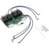
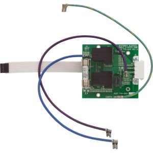
The Waterway DB-1 Daughter Board (P/N 775-0501) is a factory-original expander / daughter PCB manufactured by Waterway Plastics for the Waterway NEO 2100 Spa Control System. Its job is simple and specific: it adds one dedicated 2-speed pump output (or, per Waterway distributors, up to two additional 1-speed pump outputs) to an existing NEO 2100 main controller, enabling hot tubs configured with only Pump 1 to run a second therapy jet pump.
⚠️ Important — this is an expander board, not a standalone controller. The DB-1 cannot operate on its own. It mounts to the main NEO 2100 board using the included standoffs and harness-connects to the main PCB via dedicated terminals. You must already have a functioning Waterway NEO 2100 main controller installed for this board to be useful.
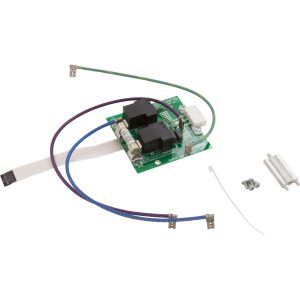
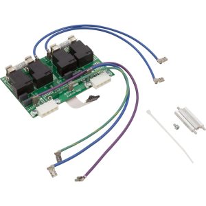
The DB-1 is shipped as a complete kit: the PCB itself plus the three 1/4″ hex #6-32 × 1.5″ standoffs, three mounting screws, and one zip tie required to mechanically install it above the main board. When installed, the system’s wiring diagram changes from Waterway drawing 777-WW00100 (base controller, no DB) to drawing 777-WW00400 (with DB1 2-Speed Daughter Board), adding relays K1 and K2 and terminals JL1/JL4 to drive the additional pump.
🌟 Key Features
- ✅ Genuine Waterway Plastics OEM daughter board – factory part manufactured specifically for the NEO Series spa control platform
- ✅ Adds a second pump – one additional 2-speed pump (Pump 2) at 240 VAC, or configurable for up to two 1-speed pumps per Waterway distributor documentation
- ✅ Drop-in mount with included hardware – PCB + (3) 1/4″ hex #6-32 × 1.5″ standoffs + (3) screws + (1) zip tie in the box
- ✅ Two dedicated onboard relays – K1 and K2 manage the low-speed and high-speed pump circuits for the added pump
- ✅ Integrates with the NEO 2100 topside panel – the Jet 2 button on the NEO 2100 control panel activates this board’s outputs once installed
- ✅ Compatible wiring diagram: 777-WW00400-A – referenced directly in the official Waterway NEO 2100 Instruction Manual (810-1930.0119)
- ✅ Cross-compatible with select NEO Series systems – per Waterway distributor documentation, the DB1 is designed for NEO Series control systems and is commonly used in NEO 2100 installations
- ✅ Made in USA – designed, engineered, and manufactured in the USA by Waterway Plastics
🔩 Technical Specifications
| Specification | Value |
|---|---|
| Manufacturer Part Number | 775-0501 |
| Type | Daughter Board / Expander PCB |
| Function | Adds 1 additional 2-speed pump (Pump 2) to NEO 2100 Main Controller |
| Parent System | Waterway NEO 2100 Spa Control System |
| Parent System Wiring Diagram (with DB1) | 777-WW00400-A |
| Onboard Relays | 2 (designated K1, K2 in Waterway wiring) |
| Key Terminals Added | JL1, JL4 (and J1 harness connection to main board) |
| Pump 2 Output | 240 VAC, 2-speed |
| Manufacturer | Waterway Plastics (Oxnard, CA, USA) |
| Kit Contents | PCB + (3) 1/4″ Hex #6-32 × 1.5″ Standoffs + (3) Screws + (1) Zip Tie |
| Approximate Physical Dimensions | 6.45″ L × 4.10″ W × 2.15″ H |
| Approximate Weight | ~0.34 lbs |
| UPC | 753610463153 |
| Warranty | Waterway Limited Warranty (see Waterway Plastics warranty terms) |
| Returnable | ⚠️ No – expander boards are non-returnable |
| Country of Origin | USA |
ℹ️ No standalone electrical ratings: Because the DB-1 is powered and controlled by the NEO 2100 main board, it does not have an independent input voltage, breaker rating, or GFCI specification of its own. All supply-side electrical specs are inherited from the NEO 2100 main controller (240 VAC, Class A GFCI, #6 AWG copper minimum).
✅ Compatibility Guide
What You Need Before Installing This Board
Before the DB-1 can be used, your spa must have all of the following:
| Requirement | Details |
|---|---|
| Main Controller | Waterway NEO 2100 Spa Control System (or Waterway NEO Series controller that supports daughter boards) |
| Open Daughter-Board Mount Position | The main board has designated standoff holes for mounting the DB-1 above the main PCB |
| Jet 2 Pump | A compatible 240 VAC 2-speed spa pump wired to the newly added JL1/JL4 terminals |
| Jet 2 Button | NEO 2100 topside panel (the JET 2 button activates the DB-1 outputs) |
| Wiring Diagram | Your installation must follow Waterway diagram 777-WW00400-A (with DB1 2-Speed Daughter Board) |
Compatible Waterway NEO Series Main Controllers
| Main Controller | Compatibility | Notes |
|---|---|---|
| Waterway NEO 2100 | ✅ Direct – primary application | 777-WW00400-A diagram applies |
| Waterway NEO 1500 (per distributor documentation) | ✅ Compatible | DB1 expander used across NEO Series systems |
| Waterway NEO 1000 | ℹ️ Verify with Parts4Tubs | Not all NEO variants accept daughter boards |
⚠️ Always match against your actual main board. Open the equipment bay, read the main board’s Waterway part number, and confirm the daughter-board mounting footprint exists before ordering.
NOT Compatible With
| System | Reason |
|---|---|
| Balboa BP-series controllers (BP100, BP501, BP2000, etc.) | Different manufacturer; use Balboa G1940 or equivalent |
| Gecko Y-series, in.xe, in.yj | Different manufacturer; use Gecko-specific expanders |
| Spa Builders LX-10 / LX-15 | Different platform (Sundance/Jacuzzi family) |
| Any non-Waterway NEO control system | This board is NEO Series–specific |
Related Waterway NEO 2100 Replacement Parts
| Part Number | Description |
|---|---|
| 775-0010b | NEO 2100 main controller board (Rev D) |
| 775-0501 | DB-1 daughter board – adds 1 additional 2-speed pump (THIS PRODUCT) |
| 775-0502 | DB-2 daughter board – adds 2 additional 2-speed pumps |
| 775-0100 | NEO 2100 temperature sensor |
| 775-0101 | NEO 2100 hi-limit sensor |
| 775-5001 | NEO 2100 5.5 kW replacement heater (H5000) |
| 775-0504 | NEO WiFi module |
| 777-WW00300 | NEO 2099/2100 keypad (topside) |
🎛️ Board Functions & Controls
What the DB-1 Adds to the Base NEO 2100 System
Base NEO 2100 system (without DB-1) – per diagram 777-WW00100: Pump 1 (2-speed, 240 VAC), Circulation Pump, Ozone, Spa Light (10 VAC), Heater (5.5 kW), Audio/Video, Optional Aux Output
Base NEO 2100 system + DB-1 (775-0501) – per diagram 777-WW00400: All of the above, PLUS Pump 2 (2-speed, 240 VAC) via K1 and K2 relays on the daughter board, accessed from the JET 2 button on the NEO 2100 / 1100 control panel
Control Panel Behavior (from NEO 2100 Manual)
After the DB-1 is installed and Pump 2 is wired to JL1/JL4, the NEO 2100 topside panel’s JET 2 button becomes functional:
- First press: Pump 2 turns on at low speed
- Second press: Pump 2 switches to high speed
- Third press: Pump 2 turns off
- Default timeouts: High speed 15 minutes, Low speed 60 minutes (both user-adjustable in the DEVICES TIMEOUT menu, max High 1 hour, max Low 2 hours)
Relay Map (777-WW00400 diagram)
| Relay | Function |
|---|---|
| K1 | Pump 2 – Low Speed |
| K2 | Pump 2 – High Speed |
Terminal Additions
| Terminal | Added With DB-1 | Function |
|---|---|---|
| JL1 | ✅ | Pump 2 wiring connection point |
| JL4 | ✅ | Pump 2 wiring connection point |
| J1 | ✅ | Harness tie-in between DB-1 and main board |
⚡ Installation Requirements
Pre-Installation Checklist
- [ ] Confirm your main controller is a Waterway NEO 2100 (or compatible NEO Series)
- [ ] Confirm your main board has the daughter-board mount position available
- [ ] Confirm you have a compatible 240 VAC 2-speed spa pump wired and ready for Pump 2
- [ ] Photograph the existing main-board layout before opening the harness
- [ ] Disconnect all power at the house breaker AND the spa disconnect box
- [ ] Allow capacitors to discharge — wait at least 5 minutes after power-off
- [ ] Have the Waterway NEO 2100 Instruction Manual (810-1930) open to the 777-WW00400 with DB1 2SPD Daughter Board diagram
Mechanical Installation (Kit Hardware)
- Install the three 1/4″ hex #6-32 × 1.5″ standoffs into the designated holes on the main NEO 2100 PCB
- Seat the DB-1 board onto the standoffs with its pin strip aligned to the main-board socket
- Secure with the three supplied screws
- Use the supplied zip tie to dress any new harness slack away from the heater and high-voltage terminals
Electrical Installation
- Wire the Pump 2 supply leads to the new JL1 and JL4 terminals per Waterway diagram 777-WW00400
- Engage the J1 harness to tie the DB-1 into the main board
- Confirm pump voltage matches the 240 VAC supply and that Pump 2 high-speed current draw is within the main system’s total amperage limit
- Verify all other wiring matches the 777-WW00400 diagram — several factory jumpers and terminal positions differ between the “without DB” (777-WW00100) and “with DB1” (777-WW00400) wiring configurations
Power-Up Sequence
- Close the control box cover
- Restore power at the disconnect, then the house breaker
- Priming Mode will run — toggle JET 2 to prime the added pump
- Press RETURN to exit Priming Mode (or wait 4 minutes)
- Confirm JET 2 button cycles Pump 2 through low → high → off
- Verify Pump 2 does not cause any Insufficient Flow or Sensor errors on the NEO display
💡 Tip: The NEO 2100 control panel includes a GENERAL INFORMATION screen that indicates which plug should be inserted into which connector — use this as a live sanity-check after installing the DB-1.
🛡️ Safety Warnings
Electrical Safety (from Waterway Instruction Manual)
- ⚠️ Qualified technician required for service and installation
- ⚠️ SHOCK HAZARD! NO USER SERVICEABLE PARTS
- ⚠️ ALWAYS disconnect power at the house breaker AND spa disconnect box before opening the control enclosure
- ⚠️ High voltage levels exist inside the control box — contact can cause injury or electrocution
- ⚠️ Connect only to a circuit protected by a Class A GFCI mounted at least 5 ft (1.52 m) from the spa’s inside walls and in line of sight from the equipment compartment (NEC Article 680)
- ⚠️ Use only #6 AWG copper conductors minimum
- ⚠️ Installation must be performed by a licensed electrician with all grounding connections properly installed
- ⚠️ Equipment and controls must be located not less than 1.5 m horizontally from the spa/hot tub (per Waterway)
Water & Electrical Safety
- ⚠️ To prevent premature control failure, do not hose down, flood, or allow water to enter the control box
- ⚠️ Inspect every seal and gasket on the enclosure before closing up
- ⚠️ Never touch electrical components with wet hands
Post-Installation
- ⚠️ Confirm no Insufficient Flow / Low Flow / Overheat / Sensor errors appear on the NEO display
- ⚠️ Verify the total output amp draw with both pumps running remains within the main system’s max input rating
- ⚠️ Monitor Pump 2 during the first full filter cycle for any error screens
📋 Error Codes & Troubleshooting (NEO 2100 Platform)
The DB-1 itself does not generate separate error codes — it operates through the NEO 2100 main controller, which will display the following NEO Series error screens on the topside panel:
| Error Message | Meaning | Typical Action |
|---|---|---|
| Insufficient Flow | No water flow through heater (or no water in heater) | Check water flow through heater; press RETURN to clear |
| Low Flow | Flow through heater insufficient for safe heating | Clean filter; check plumbing; press RETURN to clear |
| Water Overheat | Water temperature exceeded safe limit | Wait for water to cool; press RETURN to clear |
| Heater Overheat | Heater element overheated (often flow-related) | Check flow through heater; wait to cool; press RETURN to clear |
| Potential Freeze | Sensor 1, 2, or 3 detecting low temperature | No action needed — all jets and blowers will run automatically until 3 sensors reach target |
| Plumbing Error | Sensor 1 and Sensor 3 plugged into wrong positions | Swap Sensor 1 and Sensor 3 plugs at the main controller |
| Sensor 1 Open / Short | Sensor 1 fault | Check Sensor 1 connection or replace sensor |
| Sensor 2 Open / Short | Sensor 2 fault | Check Sensor 2 connection or replace sensor |
| Sensor 3 Open / Short | Sensor 3 fault | Check Sensor 3 connection or replace sensor |
If Pump 2 does not activate after DB-1 installation, the issue is almost always in the DB-1 harness / K1-K2 wiring or in the Pump 2 supply wiring to JL1/JL4 — not in the error-code system itself.
🎯 Ideal Applications
| Application | Suitability | Notes |
|---|---|---|
| Upgrading a 1-pump NEO 2100 spa to 2-pump operation | ✅ Primary application | Direct functional fit |
| Replacing a failed factory-installed DB-1 on a 2-pump NEO 2100 system | ✅ Direct replacement | Match the 777-WW00400 diagram |
| OEM spa manufacturers building 2-pump NEO 2100 systems | ✅ Genuine factory kit | Includes mounting hardware |
| Converting a single-pump spa to dual-jet therapy | ✅ Compatible | Requires a compatible 240 VAC 2-speed Pump 2 |
| Adding a 3rd pump (3-pump configuration) | ❌ Not this board – use the DB-2 (775-0502) instead, which supports 2 additional pumps | |
| Non-Waterway NEO control systems | ❌ Not compatible | |
| Use as a standalone controller | ❌ This is an expander — it is NOT a standalone controller |
This board is designed for:
- Factory and field addition of Pump 2 on Waterway NEO 2100 spa control systems
- Matched OEM replacement when a failed DB-1 needs replacement
- Retrofits where a 1-pump spa is being upgraded to dual-jet operation
💬 Frequently Asked Questions
Q: Can I use the DB-1 as a standalone controller? A: No. The DB-1 is an expander / daughter board that mounts to a Waterway NEO 2100 main board and connects via the J1 harness. You must have a functioning NEO 2100 main controller already installed.
Q: How do I know if my spa can accept the DB-1? A: Two requirements must be met: (1) your spa uses a Waterway NEO 2100 (or compatible NEO Series) main controller, and (2) the main board has the designated daughter-board mount position with standoff holes. Open your equipment bay and inspect the main PCB; contact Parts4Tubs with a photo if you are unsure.
Q: What’s in the kit? A: The PCB itself plus (3) 1/4″ hex #6-32 × 1.5″ standoffs, (3) screws, and (1) zip tie — exactly what is needed to mount the board to the NEO 2100 main controller.
Q: What’s the difference between the DB-1 and the DB-2? A: The DB-1 (775-0501) adds one additional 2-speed pump (Pump 2). The DB-2 (775-0502) adds two additional 2-speed pumps (Pump 2 and Pump 3). If your spa has three pumps, you need the DB-2, not the DB-1.
Q: Can the DB-1 drive two 1-speed pumps instead of one 2-speed pump? A: Per Waterway distributor documentation, the DB-1 is designed to allow either configuration — one additional 2-speed pump or two additional 1-speed pumps. The Waterway NEO 2100 Instruction Manual and diagram 777-WW00400 document the 2-speed configuration specifically. For dual 1-speed wiring, confirm the target spa’s pump configuration and contact Parts4Tubs for guidance before ordering.
Q: What voltage does this board run on? A: 240 VAC, inherited from the main NEO 2100 controller. The DB-1 has no independent voltage rating of its own — it operates off the main board’s power. The Pump 2 output the DB-1 drives is 240 VAC 2-speed.
Q: Do I need to change the wiring on the main board? A: Yes. The NEO 2100 wiring configuration changes from 777-WW00100-A (without DB) to 777-WW00400-A (with DB1). Several jumpers and terminal assignments differ between the two diagrams. Follow the 777-WW00400 diagram exactly.
Q: Do I need a licensed electrician? A: Yes. NEC Article 680, Waterway’s own Instruction Manual, and most local codes require a licensed electrician for spa/hot-tub electrical work. High voltage is present inside the control box and the installation is a shock hazard without proper precautions.
Q: Does this come with the Pump 2 itself? A: No. The kit includes only the DB-1 PCB and the mounting hardware needed to attach it to the main board. You must supply the compatible 240 VAC 2-speed spa pump separately.
Q: Can I return the DB-1 if it doesn’t fix my problem? A: ⚠️ No. Expander boards and other spa electrical items are non-returnable — they cannot be resold as new once installed or powered on. Please verify compatibility carefully before purchase. Waterway’s limited warranty still applies through the point of purchase if the board is defective.
Q: Where is it made? A: Waterway Plastics is headquartered in Oxnard, CA, and the company’s product literature states NEO Series controls are “Designed, Engineered & Manufactured in the USA.”
🏆 Why Choose the Waterway DB-1 (775-0501)
- ✅ Genuine Waterway Plastics OEM daughter board
- ✅ Purpose-built for the NEO 2100 platform with documented wiring diagram 777-WW00400
- ✅ Complete installation kit — PCB + standoffs + screws + zip tie
- ✅ Two dedicated relays (K1, K2) for reliable 2-speed Pump 2 switching
- ✅ Designed, engineered, and manufactured in the USA
- ✅ Backed by Waterway’s limited warranty through point of purchase
- ✅ Full integration with the NEO 2100 topside panel’s JET 2 button
- ✅ Field-proven expander used by Waterway NEO Series spa manufacturers
🛒 Why Buy From Parts4Tubs
- ✅ US-based company with local technical support
- ✅ Fast US shipping
- ✅ Expert advice from spa specialists — we’ll help you confirm your NEO 2100 main board is ready to accept the DB-1 before you order
- ✅ Competitive pricing on genuine OEM Waterway parts
- ✅ Waterway warranty support
- ✅ Matching NEO 2100 main boards, temperature sensors, hi-limit sensors, heaters, and topside panels in stock
- ✅ Help with wiring-diagram interpretation (777-WW00100 vs 777-WW00400)
✨ Summary
The Waterway DB-1 Daughter Board (775-0501) is the genuine OEM 2-speed pump expander for the Waterway NEO 2100 Spa Control System. It adds one 2-speed 240 VAC Pump 2 output (via onboard relays K1 and K2) to a base NEO 2100 main board, following the Waterway-documented 777-WW00400 wiring diagram. Shipped as a complete kit with (3) standoffs, (3) screws, and (1) zip tie. Not a standalone controller — the NEO 2100 main board is required. Designed, engineered, and manufactured in the USA by Waterway Plastics. Non-returnable — verify fit before purchase.
Finding and identifying a replacement Hot Tub Circuit Board (PCB)
If you are looking to replace a failed PCB on your Hot Tub’s spa pack, then quite often identifying the part that you need can be the hardest thing.
Firstly, you are looking for a model number on the actual circuit board itself. Having the model or serial of your hot tub is not going to help at this point, you need to find the number on the PCB itself.
Now, with certain brands of PCB, the number of the replacement PCB that you need is not going to match identically the one you are replacing. Why is that I hear you ask?
Well, normally, it is an updated version. This means that it might have updated firmware on the PCB or be a later revision. Normally, this means that the part number would be slightly different. This is usually indicated with a “12345678 -x” at the end of that part number where x indicated a firmware revision.
In some cases, there will be some following letters on the part number of the circuit board, “12345678 -x MAS” this can indicate that the PCB was used for an OEM meaning it was produced for a certain hot tub manufacturer and the letters identify the manufacturer.
This means if you source an original PCB, it will not have the letters, but will in most cases work just fine.
It can be confusing I know!
What if you can’t find a model number?
If you can’t find a model number on the PCB itself, then you need to look for a model number on the spa pack. Normally, there is a sticker on the outside of the spa pack that tells you the current ratings and input voltages etc and this will have a model number.
In general, most spa packs in the USA are manufactured by Balboa, Hydro-Quip, ACC or Gecko. I know I am generalising here, but if you have a spa pack that has the brand of your hot tub on, it will be an OEM so the key is identifying who made the original box.
From there, you can normally find an original PCB that you will be able to switch out.
For example, the Balboa VS (value series) is a very popular spa pack that has been used by multiple hot tub manufacturers under their own brand names. Whatever they have called it, strip it back and it is still a Balboa VS.
Visual Inspection
One of the most important things you can do when you are looking for a replacement is to visually inspect the PCB that you have versus the picture online of the replacement you are considering. They need to look the same even if there are the differences in firmware revisions or OEM part numbers, you should be visually replacing a PCB that looks like the one you have.
Configuring a replacement Hot Tub Circuit Board (PCB)
When you get a new PCB, you are more than likely going to need to configure it. Most PCBs have a number of different modes and setups that the can operate in. For this, you will need to manual or spec sheet to guide you.
For things like DIP switches, most of the time you can copy the settings from your original circuit board. You are looking for things like setting the voltage as a lot of PCBs can be configured to run on both 115V and 230V.
You may need to move jumpers or even wires to configure voltages – the key here is that you read the schematic and don’t expect the PCB to just work out of the box – it usually doesn’t.
Troubleshooting a Hot Tub Circuit Board (PCB)
Here are some common things you will see when you replace a PCB on a hot tub.
You press the buttons on the topside control and they don’t control the right parts (pumps or blower etc) – this is a mode configuration thing and you will either need to change some DIP switches on the PCB or an internal or low level programming mode on the topside control. Check the manual for how to do this.
You turn on the hot tub and it trips the breaker – it is not common for a new PCB to fail out of the box (I have not seen one yet!) However, a common mistake is that the voltage has not been set correctly. If it is set for 115V and then you try and turn it on, the current draw will be a lot more (twice) than expected and the breaker will trip.
To check this, unplug all of your kit – heater, pumps, blower and then turn on the PCB. If it trips with nothing plugged in, usually the voltage is incorrectly set and what is happening is that live current is being sent to the ground – because you have 4 wires into the PCB rather than 3. Current on the ground loop causes the trip. Check the settings to make sure it is configures for 230V.
It might not trip until you physically turn on a pump or a blower. As mentioned, if the pack is set to 115V and your pump is meant for 230V, it will draw twice the current at half the voltage and trip your breaker. Check the manual for info on how to set the voltage.
| Circuit Board Application | Waterway |
|---|---|
| Circuit Board Model | NEO 2100 DB-1 |
| Circuit Board Type | New |
| Manufacturers Part Number | 775-0501 |
| Circuit Board Accessory | Daughter Board |
| H Part# | 59-270-3004 |
Related products

Waterway Circuit Boards
Waterway NEO 2100 Daughter Board 2 (DB-2) – Dual 2-Speed Pump Expander Kit (P/N 775-0502)
$166.53
Waterway Circuit Boards
Waterway NEO 1500 Main Controller Board – Rev D (P/N 775-0019)
$323.99