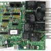
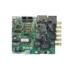

Coast Spas Circuit Board — CS504SZ (55637) — 2-Pump North American Spa Control
$369.64
Circuit Board, Coast Spa/Balboa, North American, 2-Pump Board Only
Out of stock
Want to be notified when this product is back in stock?
Fast dispatch
Order in
--:--:--
for shipping today
🔌 Coast Spas Circuit Board — CS504SZ (55637) — 2-Pump North American Spa Control
Genuine 2-pump replacement circuit board for Coast Spa systems powered by Balboa VS500Z technology.
⚠️ IMPORTANT — PLEASE READ BEFORE ORDERING
- Currently out of stock. This board (55637) is listed as out of stock at Parts4Tubs. Use the “Notify Me” option to be alerted when it becomes available.
- The original 55637 has been discontinued by Balboa. This is the original Coast Spas OEM board. The current manufacturer-recommended replacement is board 54638-01 (G1153), which is a direct drop-in replacement. If you need a replacement now, Parts4Tubs also carries the G1153 Balboa Genuine VS504SZ — contact us for guidance.
- If installing 54638-01 as a substitute: Move all white wires to match the positions on the original board. Do not move any black wires.
- Identify by board number and chip. The white sticker on your existing board should show Balboa board number 55637 and chip CS504SZUR1(x) (revision A, B, or C). The system box PN is 55636.
- Board Only — not a complete spa pack. This is the PCB only. No heater, sensors, or enclosure included.
- Do not order by appearance alone. Boards from the VS500Z family look similar but carry different software. Match by board number 55637 and chip CS504SZUR1(x).
💧 Product Overview
The Coast Spas CS504SZ circuit board (Balboa board number 55637) is an original OEM replacement PCB manufactured by Balboa Water Group for Coast Spas North American hot tub systems using the CS504SZU control system. Built on Balboa’s VS500Z platform (PCB PN 22972), this 2-pump board manages a 2-speed Pump 1, a 1-speed Pump 2, an optional 120V circulation pump, ozone, 12V spa light, 120V AV (stereo), and a 4.0kW / 240V electric heater.
The 55637 uses the Balboa Serial Standard (not Duplex) connection interface, and is compatible with the Balboa VL701S topside panel.
This is the board-only product — the complete CS504SZU spa pack system carries PN 55636.
⭐ Key Features
✅ Genuine Coast Spas OEM PCB — Balboa VS500Z platform, board PN 55637
✅ Chip CS504SZUR1(x) — North American variant; revisions R1A, R1B, R1C all covered
✅ 2-Pump configuration — 2-speed Pump 1 (240V) + 1-speed Pump 2 (240V, via J17/26 with DIP A3 ON)
✅ Optional Circulation Pump — 120V; must match ozone voltage; DIP A9 must be ON if installed
✅ 4.0kW @ 240V Heater — (approx. 1kW when running at 120V)
✅ Ozone Output — 120V factory-configured; W2 wire selectable
✅ 12V Spa Light Output
✅ 120V AV (Stereo) Output
✅ Expander Board Support — optional X-B (blower) or X-P/X-P231 (1-speed Pump 3) via DIP A7
✅ Serial Standard Topside Connection — VL701S (PN 52298-01); 8-pin
✅ Persistent Memory (J43) — battery-free storage of temp, filter settings, heat mode
✅ Dolphin Remote Compatible — full feature and spa-only models
🔧 Technical Specifications
| Specification | Value |
|---|---|
| Balboa Board PN | 55637 |
| Chip Number | CS504SZUR1(x) — North American variant; revisions R1A, R1B, R1C |
| Coast Spas System PN | 55636 (CS504SZU complete system) |
| Underlying PCB | VS500Z — PN 22972 Rev C or D |
| SSID | 100 — 93 — 43 |
| Software Version | 43 |
| System Model | VSP-VS504SZ-DCAJ |
| Board Only (not system) | Yes — board PN 55637; system PN 55636 |
| Input Voltage | 240VAC / 60Hz |
| Service Required | 40A, Class A GFCI-protected |
| Max Breaker | 50A |
| Wiring | 4-wire: Hot (Black), Hot (Red), Neutral (White), Ground |
| Heater | 4.0kW @ 240V (approx. 1kW @ 120V) |
| Pump 1 | 240V, 2-Speed |
| Pump 2 | 240V, 1-Speed — via J17/26 connector; DIP A3 must be ON |
| Circulation Pump (optional) | 120V — must match ozone voltage; DIP A9 must be ON |
| Ozone | 120V factory configured (W2 wire selectable) |
| Spa Light | 12V |
| AV (Stereo) | 120V |
| Topside Connector | Serial Standard — 8-pin (VL701S) |
| Topside panel J1/J2 note | Panels with back-lighting must connect to J1 ONLY — never J2 |
| J12 | Factory set — DO NOT MOVE (Pins 1 and 2 for VS51xZ software) |
| J43 | Persistent Memory reset: 2 pins during power-up = reset |
| Fuse F5 | CLASS G 30A |
| Fuse F7 | 20A — do not remove |
| TB1 Torque | 27–30 in. lbs. |
| Min. Wire | #6 AWG, 90°C rated (copper conductors only) |
| Stock | Out of stock |
⚠️ Ozone voltage and Circ Pump must always match. Changing the ozone voltage via W2 wire also changes the voltage at the circ pump connector (J47). Any equipment connected there must match the selected voltage.
🔗 Compatibility Guide
Compatible Coast Spas Systems:
| System | Notes |
|---|---|
| Coast Spas CS504SZU (55636) | Primary system — chip CS504SZUR1(x) |
How to Identify Your Board:
- Open spa equipment compartment and locate the circuit board
- Find the white sticker on or near the board:
- Board number: 55637
- Chip number: CS504SZUR1(x) — revision A, B, or C
- Confirm both before ordering
Compatible Topside Panel:
| Panel PN | Description | Connection Note |
|---|---|---|
| 52298-01 (VL701S) | Serial Standard — 7-button | Connect to J1. If back-lighting (bulbs) installed, use J1 ONLY — never J2 |
| VX20 | 2-button auxiliary panel | When A3 is ON |
| VX40S | 4-button auxiliary panel | — |
Current Replacement (Original 55637 discontinued):
| Part Number | Description | Notes |
|---|---|---|
| 54638-01 / G1153 | Balboa Genuine VS504SZ — current replacement | Direct drop-in; move white wires to match original positions; do not move black wires |
| 55636 | CS504SZU complete spa pack system | — |
| CS504SZUR1A, R1B, R1C | All chip revisions this board covers | — |
| CS514SZR1(x) | Related chip designation | — |
🎛️ Board Functions & Controls
DIP Switch Summary (Switchbank A):
| Switch | OFF | ON |
|---|---|---|
| A1 | Test Mode OFF (normal) | Test Mode ON |
| A2 + A10 | Heat disable table (see below) | Heat disable table |
| A3 | J17/26 (Pump 2) disabled | J17/26 (Pump 2) enabled — required for 2-pump use |
| A4 | Normal — must remain OFF | Aux Freeze |
| A5 + A9 | Pump 1 speed / Circ mode (see below) | See below |
| A6 | 60Hz (US standard) | 50Hz |
| A7 | Expander board disabled | Expander board enabled (for blower or 1-speed Pump 3) |
| A8 | Fahrenheit | Celsius |
Heat Disable Table (A2 + A10):
| A2 | A10 | HS Pumps/Blower Before Heat Disabled |
|---|---|---|
| OFF | OFF | 0 |
| ON | OFF | 1 |
| OFF | ON | 2 |
| ON | ON | 3 |
Pump 1 Speed / Circ Mode Table (A5 + A9):
| A5 | A9 | Circ Mode | Pump 1 Speed |
|---|---|---|---|
| OFF | OFF | Non-circ | 2-Speed |
| ON | OFF | Circ acts like P1 Low | 1-Speed |
| OFF | ON | 24hr with 3°F shutoff | 1-Speed |
| ON | ON | 24hr with 3°F shutoff | 2-Speed |
Expander Board Options (when DIP A7 is ON):
| Expander Board | Use |
|---|---|
| X-B | Blower |
| X-P or X-P231 | 1-speed Pump 3 (depending on amperage requirements) |
Key Jumpers:
| Jumper | Function |
|---|---|
| J12 | DO NOT MOVE — factory set on Pins 1 and 2 for VS51xZ/VS52xZ/VS5xxSZ/VS5xxDZ software |
| J43 | Persistent Memory: 2 pins during power-up = reset; 1 pin = memory enabled |
🛠️ Installation Requirements
⚠️ Installation must be performed by a licensed electrician in compliance with NEC and all applicable local codes.
Pre-Installation Checklist:
- [ ] Confirm board number 55637 and chip CS504SZUR1(x) on existing board
- [ ] Note all DIP switch positions before removal — photograph the board
- [ ] Note existing light connector position on J1 or J2
- [ ] Confirm ozone and circ pump voltage setup
- [ ] Disconnect all power at GFCI breaker or disconnect
- [ ] Allow 5 minutes for capacitor discharge after power-off
- [ ] Photograph all wiring before removal
If installing 54638-01 as substitute for the discontinued 55637:
- [ ] Move all white wires to match the original board’s white wire positions
- [ ] Do NOT move any black wires
Electrical Requirements:
| Requirement | Specification |
|---|---|
| Supply Voltage | 240VAC / 60Hz |
| Service Amperage | 40A |
| Max Breaker | 50A |
| Wiring | 4-wire: Hot (Black), Hot (Red), Neutral (White), Ground |
| GFCI | Class A GFCI required — NEC Article 680 |
| Ground & Bonding | Required — NEC Article 680 |
| Dedicated Circuit | Required |
| Disconnect Box | Within line of sight, at least 5 ft from spa |
| Wire Type | Copper conductors ONLY, #6 AWG min., 90°C rated |
| TB1 Torque | 27–30 in. lbs. |
⚠️ Safety Warnings
- ⚠️ ALWAYS disconnect all power before circuit board work
- ⚠️ Licensed electrician installation required; NEC Article 680 compliance mandatory
- ⚠️ Class A GFCI required; 40A service, 50A max breaker; grounding and bonding required
- ⚠️ J12 must NOT be moved — factory set on Pins 1 and 2; moving causes system malfunction
- ⚠️ Fuse F7 (20A) must NOT be removed
- ⚠️ Ozone and Circ Pump must be the same voltage — W2 wire change affects both
- ⚠️ DIP A4 (Aux Freeze) must always remain OFF
- ⚠️ DIP A9 must be ON if a Circ Pump is installed
- ⚠️ Panels with back-lighting must connect to J1 ONLY — plugging a back-lit panel into J2 damages the panel
- ⚠️ Reset Persistent Memory (J43) after any DIP switch change (except A1)
- ⚠️ Identify by chip CS504SZUR1(x) and board PN 55637 — not by appearance
- ⚠️ Currently out of stock — use the Notify Me option or contact Parts4Tubs for alternatives
❓ Frequently Asked Questions
Q: This board is out of stock — what can I do? A: Use the “Notify Me” button on the product page to be alerted when stock returns. Alternatively, contact Parts4Tubs — the current direct replacement is the Balboa Genuine VS504SZ (54638-01 / G1153), which is a drop-in substitute. When installing it, move all white wires to match the original 55637 positions but do not move any black wires.
Q: How do I confirm this is the right board for my Coast Spa? A: Check your existing circuit board for the white sticker. The board number should show 55637, and the chip number should show CS504SZUR1(x) (revision A, B, or C). The system box PN is 55636. Confirm both numbers before ordering.
Q: Does this board support a second pump? A: Yes, but you must set DIP A3 to ON to enable the J17/26 connector for the 1-speed Pump 2. Without A3 ON, Pump 2 will not operate.
Q: Can I use a Dolphin remote with this system? A: Yes. The VS504SZ system supports both the Full Feature Dolphin Remote and the Spa-only Dolphin Remote, as well as the optional IR Receiver Module.
Q: What topside panel works with this board? A: The Balboa VL701S (Serial Standard, PN 52298-01) is the compatible topside. It connects to terminal J1. If the panel has back-lighting (bulbs), use J1 ONLY — never J2.
Q: What happens if I change DIP switches? A: Any DIP switch change other than A1 requires a Persistent Memory reset via J43. Failure to reset will cause the spa to function improperly with the old settings.
Q: What warranty is included? A: Contact Parts4Tubs for current warranty terms applicable to the 55637 board.
✅ Why Choose the Coast Spas CS504SZ (55637)
✅ Genuine Coast Spas OEM board — Balboa VS500Z platform, factory-programmed for CS504SZU systems
✅ All CS504SZUR1 chip revisions covered — R1A, R1B, R1C
✅ 2-pump + optional circ + expander support — comprehensive multi-component spa control
✅ 4.0kW heater control at 240V
✅ Dolphin remote and IR receiver compatible
✅ PDF tech sheet available for full wiring and configuration guidance
🤝 Why Buy from Parts4Tubs
✅ Fast US shipping
✅ Expert technical advice from Coast Spas and Balboa specialists
✅ Chip and compatibility verification before ordering
✅ Competitive pricing
✅ Replacement options available — 54638-01 / G1153 and topside VL701S
✅ Parts4Tubs can help confirm whether the 55637 or the G1153 replacement is right for your repair
💡 Summary
The Coast Spas CS504SZ circuit board (55637) is a genuine OEM PCB manufactured by Balboa Water Group on the VS500Z platform for North American Coast Spa CS504SZU control systems. It is a 2-pump board controlling a 2-speed Pump 1 (240V), 1-speed Pump 2 (240V via J17/26 with DIP A3 ON), optional 120V circ pump, 120V ozone, 12V light, 120V AV stereo, and a 4.0kW / 240V heater. Service is 240VAC / 40A / 50A max breaker. Critical installation rules: J12 must not be moved; Fuse F7 must not be removed; DIP A4 must be OFF; DIP A9 must be ON if circ pump is installed; ozone and circ pump must be the same voltage; back-lit topside panels connect to J1 only. This board is currently out of stock and the original has been discontinued — the current direct replacement is 54638-01 / G1153.
Finding and identifying a replacement Hot Tub Circuit Board (PCB)
If you are looking to replace a failed PCB on your Hot Tub’s spa pack, then quite often identifying the part that you need can be the hardest thing.
Firstly, you are looking for a model number on the actual circuit board itself. Having the model or serial of your hot tub is not going to help at this point, you need to find the number on the PCB itself.
Now, with certain brands of PCB, the number of the replacement PCB that you need is not going to match identically the one you are replacing. Why is that I hear you ask?
Well, normally, it is an updated version. This means that it might have updated firmware on the PCB or be a later revision. Normally, this means that the part number would be slightly different. This is usually indicated with a “12345678 -x” at the end of that part number where x indicated a firmware revision.
In some cases, there will be some following letters on the part number of the circuit board, “12345678 -x MAS” this can indicate that the PCB was used for an OEM meaning it was produced for a certain hot tub manufacturer and the letters identify the manufacturer.
This means if you source an original PCB, it will not have the letters, but will in most cases work just fine.
It can be confusing I know!
What if you can’t find a model number?
If you can’t find a model number on the PCB itself, then you need to look for a model number on the spa pack. Normally, there is a sticker on the outside of the spa pack that tells you the current ratings and input voltages etc and this will have a model number.
In general, most spa packs in the USA are manufactured by Balboa, Hydro-Quip, ACC or Gecko. I know I am generalising here, but if you have a spa pack that has the brand of your hot tub on, it will be an OEM so the key is identifying who made the original box.
From there, you can normally find an original PCB that you will be able to switch out.
For example, the Balboa VS (value series) is a very popular spa pack that has been used by multiple hot tub manufacturers under their own brand names. Whatever they have called it, strip it back and it is still a Balboa VS.
Visual Inspection
One of the most important things you can do when you are looking for a replacement is to visually inspect the PCB that you have versus the picture online of the replacement you are considering. They need to look the same even if there are the differences in firmware revisions or OEM part numbers, you should be visually replacing a PCB that looks like the one you have.
Configuring a replacement Hot Tub Circuit Board (PCB)
When you get a new PCB, you are more than likely going to need to configure it. Most PCBs have a number of different modes and setups that the can operate in. For this, you will need to manual or spec sheet to guide you.
For things like DIP switches, most of the time you can copy the settings from your original circuit board. You are looking for things like setting the voltage as a lot of PCBs can be configured to run on both 115V and 230V.
You may need to move jumpers or even wires to configure voltages – the key here is that you read the schematic and don’t expect the PCB to just work out of the box – it usually doesn’t.
Troubleshooting a Hot Tub Circuit Board (PCB)
Here are some common things you will see when you replace a PCB on a hot tub.
You press the buttons on the topside control and they don’t control the right parts (pumps or blower etc) – this is a mode configuration thing and you will either need to change some DIP switches on the PCB or an internal or low level programming mode on the topside control. Check the manual for how to do this.
You turn on the hot tub and it trips the breaker – it is not common for a new PCB to fail out of the box (I have not seen one yet!) However, a common mistake is that the voltage has not been set correctly. If it is set for 115V and then you try and turn it on, the current draw will be a lot more (twice) than expected and the breaker will trip.
To check this, unplug all of your kit – heater, pumps, blower and then turn on the PCB. If it trips with nothing plugged in, usually the voltage is incorrectly set and what is happening is that live current is being sent to the ground – because you have 4 wires into the PCB rather than 3. Current on the ground loop causes the trip. Check the settings to make sure it is configures for 230V.
It might not trip until you physically turn on a pump or a blower. As mentioned, if the pack is set to 115V and your pump is meant for 230V, it will draw twice the current at half the voltage and trip your breaker. Check the manual for info on how to set the voltage.
| Brand | Coast Spa |
|---|
Related products
Hydro-Quip Spa Controls
Hydro-Quip Outdoor Series 5.5kW 230V Flow Thru Heater 26-0053-F-M7-KS
$185.33
Sundance Topside Controls
$319.99
Gecko Spa Pack Controls
$343.01
Sundance Topside Controls
$330.25
Hydro-Quip Heaters
$571.01
Hydro-Quip Heaters
Hydro-Quip Outdoor Series 11kW 230V Flow Thru Heater 26-0054AF-M7-KS
$266.99
Hydro-Quip Spa Controls
Hydro-Quip 6000 Series Spa Control Flow Thru Heater CS6200Y-U-WP
$672.91
Watkins Topside Controls
$142.03