


HydroQuip® PS6502B Replacement Circuit Board — Balboa VS501Z | 54357-03
$299.08
36 in stock
Fast dispatch
Order in
--:--:--
for shipping today
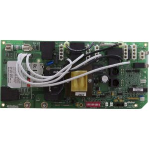
💡 HydroQuip® PS6502B Replacement Circuit Board — Balboa VS501Z | 54357-03
Genuine Balboa® VS501Z replacement PCB for HydroQuip PS6502B spa control systems — used in HydroQuip 4200B and 6200B Series portable spa packs.
⚠️ IMPORTANT — PLEASE READ BEFORE ORDERING
- Chip number identification is mandatory. Locate the chip number on the white sticker near the center of your existing board before ordering. Do not order based on appearance alone.
- ⚠️ Two nearly identical chip variants exist for this product. The chip number on your board is either INF107R* (with the number “1” as the fourth character) or INFI07R* (with the letter “I” as the fourth character). These two identifiers appear almost identical depending on the font on your board label but correspond to two distinct chip variants. Check carefully before ordering.
- DIP switch configuration required. This board is configurable for 120V or 240V operation and for blower or second-pump use. Correct configuration requires reading the included wiring diagram and performing a Persistent Memory reset after DIP switch changes.
- J17/26 output is required. The PS6502B uses VS501Z circuitry and requires either a blower or a 1-speed Pump 2 connected to J17/26. If your system does not have either, this is not the correct board.
📋 Product Overview
The HydroQuip® PS6502B circuit board is the replacement PCB for HydroQuip PS6502B spa control systems, used in HydroQuip 4200B and 6200B Series spa packs with Mini Duplex topside panels. Internally this board is based on the Balboa VS501Z platform, with Balboa PN 54357-03 (updated revision: 54357-04). HydroQuip markets and supplies this board under part numbers 33-0032B and 33-54357-K.
The VS501Z platform on which this board is based supports a 2-speed primary pump and either a blower or a 1-speed secondary pump, configurable to 120V or 240V via DIP switches. It uses M7 technology and does not require a pressure switch. The board supports ozonator, 12V spa light, fiber optic lighting, stereo (AV) output, and optional circulation pump.
✨ Key Features
✅ Genuine Balboa® VS501Z PCB — OEM board for HydroQuip PS6502B systems
✅ HydroQuip Part Numbers: 33-0032B / 33-54357-K
✅ Balboa Part Number: 54357-03 (updated revision: 54357-04)
✅ For HydroQuip 4200B and 6200B Series systems — Mini Duplex topside format
✅ Pump 1: 2-speed — 120V or 240V configurable
✅ J17/26 output: Blower OR 1-speed Pump 2 (DIP switch selectable)
✅ Ozonator/UVC output
✅ 12V Spa Light
✅ Fiber optic lighting output
✅ Stereo (AV) output
✅ Optional Circulation (Circ) Pump
✅ 115V / 230V configurable via DIP switches
✅ No pressure switch required — M7 technology
✅ Factory-new — never installed
✅ 1-year limited manufacturer’s warranty
⚠️ J17/26 required — Blower or 1-speed Pump 2 must be connected. For systems with no blower and no Pump 2, a different board is required.
⚙️ Technical Specifications
All electrical specifications are from the official Balboa VS501Z Tech Sheet (54379-04_97_B).
| Specification | Value |
|---|---|
| HydroQuip Part Numbers | 33-0032B / 33-54357-K / 33-0032B-K |
| Balboa Part Number | 54357-03 (current revision: 54357-04) |
| System | HydroQuip PS6502B |
| Compatible Series | HydroQuip 4200B and 6200B Series |
| Topside Format | Mini Duplex |
| Input Voltage | 115V / 230V (60Hz) |
| Service Amperage | 16A (115V) / 32A (230V) |
| Circuit Breaker Max | 20A (115V) / 40A (230V) |
| Wiring | 3 or 4 wire (hot, hot optional, neutral, ground) |
| GFCI | Class A GFCI-protected service required |
| Heater Output | 1.0kW @ 115V / 4.0kW @ 230V |
| Pump 1 | 2-Speed |
| J17/26 Output | Blower (Setup 1 & 2) or 1-Speed Pump 2 (Setup 3) |
| Ozonator | Supported — same voltage as Circ Pump |
| Circ Pump | Optional — same voltage as Ozone |
| Spa Light | 12V |
| Fiber Optic | Supported |
| Stereo (AV) | Supported |
| TB1 Torque Range | 27–30 in. lbs. |
| Pressure Switch | Not required (M7 technology) |
| Warranty | 1-year limited manufacturer’s warranty |
| Returns | Non-returnable |
🎛️ Board Configurations (DIP Switch Setups)
All setup specifications are from the official Balboa VS501Z Tech Sheet (54379-04_97_B). These setups apply to the VS501Z PCB used in all PS6502B systems.
Setup 1 — As Manufactured (120V/115V)
| Component | Specification |
|---|---|
| Pump 1 | 120V, 2-Speed |
| J17/26 | 120V Blower |
| Ozone | 120V (optional, same V as circ) |
| Spa Light | 12V |
| Stereo (AV) | 120V |
| Heater | 120V 1.0kW (rated 4.0kW @ 240V) |
| Circ Pump | 120V (optional) |
| Circuit Breaker | 20A |
Setup 2 — 240V/230V with Blower
| Component | Specification |
|---|---|
| Pump 1 | 240V, 2-Speed |
| J17/26 | 240V Blower |
| Ozone | 240V (optional) |
| Spa Light | 12V |
| Stereo (AV) | 240V |
| Heater | 240V 4.0kW |
| Circ Pump | 240V (optional) |
| Circuit Breaker | 40A |
Setup 3 — 240V/230V with Pump 2 (1-Speed)
| Component | Specification |
|---|---|
| Pump 1 | 240V, 2-Speed |
| J17/26 | 240V Pump 2, 1-Speed |
| Ozone | 240V (optional) |
| Spa Light | 12V |
| Stereo (AV) | 240V |
| Heater | 240V 4.0kW |
| Circ Pump | 240V (optional) |
| Circuit Breaker | 40A |
⚠️ Ozone and Circ Pump must always be the same voltage.
🔩 DIP Switch Reference
⚠️ ALWAYS power down before adjusting DIP switches. Reset Persistent Memory (J43) after any change except A1.
| Switch | ON Position | OFF Position |
|---|---|---|
| A1 | Test Mode ON | Test Mode OFF (normal) |
| A2 | Standard mode only | Std/Ecn/Sleep modes allowed |
| A3 | Mini Panel selected | Digital Duplex or Light Duplex panel |
| A4 | Must remain OFF | — |
| A5+A9 | See combined table below | — |
| A6 | 50Hz operation | 60Hz operation |
| A7 | P1, Lt, Temp↓, Temp↑ w/ J17/26 on 1-btn Aux | J17/26, P1, Temp, Light |
| A8 | Temperature in °C | Temperature in °F |
| A10 | Low Amp — heater off while high-speed pump/blower runs | High Amp — heater can run with pump/blower |
A5 + A9 Combined — Pump 1 and Circ Mode:
| A5 | A9 | Circ Mode | Pump 1 Speed |
|---|---|---|---|
| OFF | OFF | Non-circ | 2-speed |
| ON | OFF | Circ acts like P1 low | 1-speed |
| OFF | ON | 24hr circ w/ 3°F shut-off | 1-speed |
| ON | ON | 24hr circ w/ 3°F shut-off | 2-speed |
Jumper Settings:
| Jumper | Setting |
|---|---|
| J12 — Pins 1-2 | VS51xZ / VS5xxSZ / VS5xxDZ software |
| J12 — Pins 2-3 | VS50xZ software |
| J43 | Persistent Memory Reset |
🔗 Compatibility Guide
Compatible HydroQuip Systems:
| System | Series |
|---|---|
| HydroQuip PS6502B | PS6502B / 4200B / 6200B Series |
| HydroQuip CS4200B | 4200B Series |
| HydroQuip CS6200B | 6200B Series |
Replaces These Part / Chip Numbers:
| Part / Chip Number | Notes |
|---|---|
| 33-0032B | HydroQuip MFR PN for PS6502B |
| 33-0032B-K | HydroQuip kit variant |
| 33-54357-K | HydroQuip PN — VS501Z platform |
| 54357 / 54357-01 / 54357-03 | Balboa board revisions |
| LZM2UR1x | Cross-reference |
| 600-6293 | Cross-reference |
| 167R1B / 330032B / 54294-01 | Cross-references |
| 9710-71 / BB54357 | Cross-references |
| GVS501R1A / OS501ZR1A / SCS501R1A | Chip cross-refs |
| VS501R1B / VS501ZR1 / VS501ZR2B | Chip cross-refs |
| VS240RR / VKV502R1 | Chip cross-refs |
| INF107R* (number “1”) | Chip family — this product |
| INFI07R* (letter “I”) | Chip variant — verify carefully |
Compatible Topside Panels (Mini Duplex format):
| Part Number | Description |
|---|---|
| 52144 | VL200 Mini Bath Panel |
| 54094 | VL401 LCD Lite Duplex |
| 51676-01 | VL403 LED Lite Digital |
🛠️ Installation Requirements
⚠️ Installation must be performed by a licensed electrician in compliance with NEC and all applicable local codes.
Pre-Installation Checklist:
- [ ] Locate the chip number on your existing board (white sticker, center of board)
- [ ] Identify whether chip is INF107R* (number “1”) or INFI07R* (letter “I”)
- [ ] Confirm system is HydroQuip PS6502B, CS4200B, or CS6200B
- [ ] Confirm J17/26 has either a blower or 1-speed Pump 2 connected
- [ ] Confirm J12 jumper position (VS50xZ = Pins 2-3)
- [ ] Confirm voltage (115V or 230V) and which setup your system uses
- [ ] Record and photograph all DIP switch positions before removal
- [ ] Photograph all wiring connections before removal
- [ ] Disconnect all power at GFCI breaker or service disconnect
- [ ] Wait 5 minutes for capacitor discharge after power disconnect
Electrical Requirements:
| Requirement | Specification |
|---|---|
| Supply Voltage | 115V or 230V / 60Hz |
| Service Amperage | 16A (115V) / 32A (230V) |
| Circuit Breaker | 20A max (115V) / 40A max (230V) |
| GFCI | Class A GFCI required — NEC Article 680 |
| Ground & Bonding | Required — NEC Article 680 |
| Dedicated Circuit | Required |
| Disconnect Box | Within line of sight of spa, at least 5 ft away |
| Wire Type | Copper conductors only |
| TB1 Torque | 27–30 in. lbs. |
⚠️ Safety Warnings
- ⚠️ ALWAYS disconnect all power before circuit board work — allow 5 minutes for capacitor discharge
- ⚠️ Licensed electrician installation required; NEC Article 680 compliance mandatory
- ⚠️ Class A GFCI required; grounding and bonding required per NEC Article 680
- ⚠️ Do NOT order based on appearance alone — chip number determines compatibility
- ⚠️ INF107R* (number “1”) vs INFI07R* (letter “I”) — check character carefully before ordering
- ⚠️ Persistent Memory (J43) must be reset after any DIP switch change (except A1)
- ⚠️ J17/26 requires blower or Pump 2 — if neither is present, this is the wrong board
- ⚠️ Do not remove Fuse F7 (20A)
- ⚠️ Ozone and Circ Pump must be the same voltage
- ⚠️ Damage from incorrect installation is NOT covered under warranty
- ⚠️ Non-returnable — verify chip number and compatibility before ordering
❓ Frequently Asked Questions
Q: What is the HydroQuip PS6502B? A: The HydroQuip PS6502B is a spa control system used in HydroQuip 4200B and 6200B Series portable spas. It is based on the Balboa VS501Z platform with a Mini Duplex topside format. This product is the replacement circuit board for that system.
Q: What is the difference between INF107R* (number “1”) and INFI07R* (letter “I”)? A: These are two chip number variants that appear almost identical due to font similarity between the number “1” and the letter “I.” Both are covered by the 54357-03 board family, but they are distinct chip identifiers. Always read the chip number carefully — ideally under magnification — to confirm which character appears as the fourth position in the code.
Q: What is the difference between 33-0032B and 33-54357-K? A: Both are HydroQuip part numbers for the VS501Z-based board used in PS6502B-related systems. The 33-0032B is the HydroQuip direct PN for the PS6502B board. The 33-54357-K is the HydroQuip universal designation for the Balboa VS501Z board across their 4200B/6200B platform. Either can be used to identify this product.
Q: What topside panel does the PS6502B use? A: The PS6502B uses Mini Duplex format topsides. Compatible panels include the VL200 Mini Bath (52144), VL401 LCD Lite Duplex (54094), and VL403 LED Lite Digital (51676-01).
Q: Does this board require a pressure switch? A: No. The VS501Z uses M7 technology and does not require a pressure switch.
Q: What warranty is included? A: 1-year limited manufacturer’s warranty. Damage from incorrect installation, freezing, low voltage, or chemical abuse is not covered. Circuit boards are non-returnable.
✅ Why Choose the HydroQuip® PS6502B Board (54357-03)
✅ Genuine Balboa® VS501Z PCB — factory original, never installed
✅ Correct HydroQuip PS6502B designation — 33-0032B / 33-54357-K
✅ 4200B and 6200B Series compatible — Mini Duplex topside format
✅ 115V / 230V configurable via DIP switches
✅ Three setup options — P1+Blower (115V or 230V) or P1+P2 1-speed (230V)
✅ M7 technology — no pressure switch needed
✅ Official Balboa documentation available
✅ 1-year limited manufacturer’s warranty
🤝 Why Buy from Parts4Tubs
✅ US-based company with expert knowledge of HydroQuip PS6502B and VS501Z systems
✅ Fast US shipping
✅ Chip number verification support — contact us before ordering if unsure
✅ Compatible Mini Duplex topside panels available
✅ Competitive pricing
🔌 Summary
The HydroQuip® PS6502B circuit board (Balboa VS501Z, 54357-03) is the OEM replacement PCB for HydroQuip PS6502B spa control systems used in 4200B and 6200B Series portable spas with Mini Duplex topsides. HydroQuip part numbers are 33-0032B and 33-54357-K. The board is configurable for 115V or 230V operation and supports 2-speed Pump 1 with either a blower or 1-speed Pump 2 on J17/26, plus ozone, 12V light, fiber optics, AV, and optional circ pump. Heater output: 1.0kW @ 115V / 4.0kW @ 230V. Always verify your board’s chip number — note the critical INF107R* (number “1”) vs INFI07R* (letter “I”) distinction. Non-returnable; 1-year manufacturer’s warranty.
Finding and identifying a replacement Hot Tub Circuit Board (PCB)
If you are looking to replace a failed PCB on your Hot Tub’s spa pack, then quite often identifying the part that you need can be the hardest thing.
Firstly, you are looking for a model number on the actual circuit board itself. Having the model or serial of your hot tub is not going to help at this point, you need to find the number on the PCB itself.
Now, with certain brands of PCB, the number of the replacement PCB that you need is not going to match identically the one you are replacing. Why is that I hear you ask?
Well, normally, it is an updated version. This means that it might have updated firmware on the PCB or be a later revision. Normally, this means that the part number would be slightly different. This is usually indicated with a “12345678 -x” at the end of that part number where x indicated a firmware revision.
In some cases, there will be some following letters on the part number of the circuit board, “12345678 -x MAS” this can indicate that the PCB was used for an OEM meaning it was produced for a certain hot tub manufacturer and the letters identify the manufacturer.
This means if you source an original PCB, it will not have the letters, but will in most cases work just fine.
It can be confusing I know!
What if you can’t find a model number?
If you can’t find a model number on the PCB itself, then you need to look for a model number on the spa pack. Normally, there is a sticker on the outside of the spa pack that tells you the current ratings and input voltages etc and this will have a model number.
In general, most spa packs in the USA are manufactured by Balboa, Hydro-Quip, ACC or Gecko. I know I am generalising here, but if you have a spa pack that has the brand of your hot tub on, it will be an OEM so the key is identifying who made the original box.
From there, you can normally find an original PCB that you will be able to switch out.
For example, the Balboa VS (value series) is a very popular spa pack that has been used by multiple hot tub manufacturers under their own brand names. Whatever they have called it, strip it back and it is still a Balboa VS.
Visual Inspection
One of the most important things you can do when you are looking for a replacement is to visually inspect the PCB that you have versus the picture online of the replacement you are considering. They need to look the same even if there are the differences in firmware revisions or OEM part numbers, you should be visually replacing a PCB that looks like the one you have.
Configuring a replacement Hot Tub Circuit Board (PCB)
When you get a new PCB, you are more than likely going to need to configure it. Most PCBs have a number of different modes and setups that the can operate in. For this, you will need to manual or spec sheet to guide you.
For things like DIP switches, most of the time you can copy the settings from your original circuit board. You are looking for things like setting the voltage as a lot of PCBs can be configured to run on both 115V and 230V.
You may need to move jumpers or even wires to configure voltages – the key here is that you read the schematic and don’t expect the PCB to just work out of the box – it usually doesn’t.
Troubleshooting a Hot Tub Circuit Board (PCB)
Here are some common things you will see when you replace a PCB on a hot tub.
You press the buttons on the topside control and they don’t control the right parts (pumps or blower etc) – this is a mode configuration thing and you will either need to change some DIP switches on the PCB or an internal or low level programming mode on the topside control. Check the manual for how to do this.
You turn on the hot tub and it trips the breaker – it is not common for a new PCB to fail out of the box (I have not seen one yet!) However, a common mistake is that the voltage has not been set correctly. If it is set for 115V and then you try and turn it on, the current draw will be a lot more (twice) than expected and the breaker will trip.
To check this, unplug all of your kit – heater, pumps, blower and then turn on the PCB. If it trips with nothing plugged in, usually the voltage is incorrectly set and what is happening is that live current is being sent to the ground – because you have 4 wires into the PCB rather than 3. Current on the ground loop causes the trip. Check the settings to make sure it is configures for 230V.
It might not trip until you physically turn on a pump or a blower. As mentioned, if the pack is set to 115V and your pump is meant for 230V, it will draw twice the current at half the voltage and trip your breaker. Check the manual for info on how to set the voltage.
| Circuit Board Application | Balboa Water Group |
|---|---|
| Circuit Board Model | PS6502B Series |
| Circuit Board Type | New |
| Manufacturers Part Number | 54357-03 |
| H Part# | 59-355-1683 |
Related products
Out of stock
$483.37
Sundance Circuit Boards
⚙️ Sundance® / Jacuzzi® 6600-390 880 NT System Spa Circuit Board (2-Pump with PermaClear®)
$966.39
$481.65
Out of stock
Gecko Heating
$112.64
Hydro-Quip Spa Controls
Hydro-Quip Outdoor Series 5.5kW 230V Flow Thru Heater 26-0053-F-M7-KS
$185.33
Balboa Circuit Boards
Coleman / MAAX 100 Series Spa Circuit Board — 101285 (Chip 115/7R1x)
$463.36
Sundance Topside Controls
$319.99
Out of stock
ACC Overlays
$199.66